Protection circuit assembly and method

a protection circuit and circuit technology, applied in the field of electric circuits, can solve the problems of increasing the cost of implementing or establishing a dali lighting system, controllers may receive too much voltage via the control bus, damage or destruction, etc., and achieve the effect of preventing an increase of voltag

Active Publication Date: 2017-10-19
GE LIGHTING SOLUTIONS LLC
View PDF0 Cites 10 Cited by
  • Summary
  • Abstract
  • Description
  • Claims
  • Application Information

AI Technical Summary

Benefits of technology

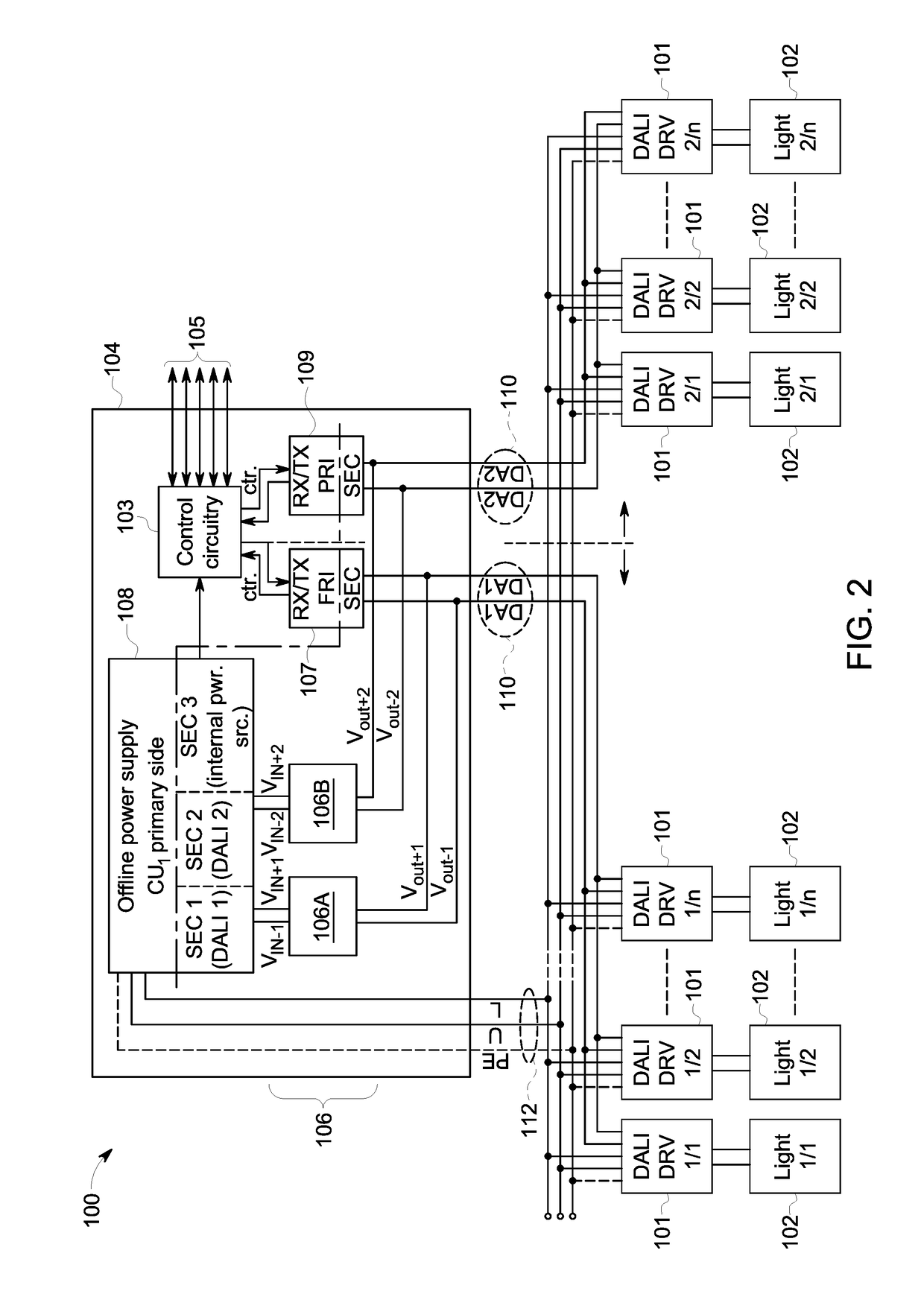
[0005]In one embodiment, a lighting system includes plural protection circuits configured to be conductively coupled with a power supply that supplies current to plural light sources to power the light sources. The protection circuits are configured to receive an input voltage from the power supply and to conduct an output voltage to separate control buses that are conductively coupled with drivers of the light sources to conduct control signals to the drivers of the light sources for control of operation of the light sources. The system also includes a microcontroller configured to generate the control signals to control the operation of the light sources and plural transceiving circuits configured to receive the control signals from the microcontroller and to conduct the control signals to different groups of the light sources via the separate control buses. The protection circuits are separately connected to the separate control buses to conduct the output voltage from the power supply to the light sources. The protection circuits are configured to prevent an increase of voltage on a first control bus of the control buses from increasing voltage on a different, second control bus of the control buses.
[0006]In one embodiment, a method includes receiving an input voltage from a power supply at plural protection circuits conductively coupled with the power supply to supply current to plural light sources to power the light sources, conducting an output voltage from the protection circuits to separate control buses that are conductively coupled with drivers of the light sources, and communicating control signals from a microcontroller to the drivers of the light sources via plural transceiving circuits and the control buses for control of operation of the light sources. The control signals can be separately communicated to different groups of the light sources via the separate control buses for separate control of the different groups of the light sources. The method also can include preventing (with the protection circuits) an increase of voltage on a first control bus of the control buses from increasing voltage on a different, second control bus of the control buses.

Problems solved by technology

This can cause the light source to be miswired to the controller, such as when the mains voltage line and the control bus are incorrectly connected to the controller to connections intended for the other of the control bus or the mains voltage line.
As a result, the controller may receive too much voltage via the control bus and be damaged or destroyed by the voltage.
This can significantly increase the cost of implementing or establishing a DALI lighting system.

Method used


Image

  • Protection circuit assembly and method
  • Protection circuit assembly and method
  • Protection circuit assembly and method

Examples


Embodiment Construction

[0017]FIG. 1 illustrates a lighting control system 800 according to one example. The lighting control system 800 includes a lighting controller 802 (e.g., “DALI lighting controller” in FIG. 1) that controls operation of several light sources 804 (e.g., “Light source 1,”“Light source 2,” Light source 3,” and “Light source 64” in FIG. 1) via control signals communicated to corresponding lighting drivers 806 (e.g., “DALI lighting driver 1,”“DALI lighting driver 2,”“DALI lighting driver 3,” and “DALI lighting driver 64” in FIG. 1). A power supply 808 (“DALI power supply” in FIG. 1) powers the light sources 804 by conducting electric current to the light sources 804. The lighting system 800 can represent a digital addressable lighting interface (DALI) lighting system. The lighting system 800 includes several conductive buses for conducting control signals from the controller 802 to the drivers 806 and for conducting electric current from the power supply 808 to the light sources 804. The...


PUM


Abstract

Single channel digital addressable lighting interface (DALI) systems can include a dedicated external power supply that operates in a constant voltage/constant current mode to meet requirements of the DALI bus. A lighting controller is powered from the DALI bus. In one embodiment of the inventive subject matter, a lighting system is provided that includes two or more control (e.g., DALI) buses and a multichannel power supply that can be used for powering a controller of the system with constant voltage and to power separate control buses with separate and constant current. In order to protect the controller and buses from overloads caused by miswiring or other erroneous conditions, a protection circuit assembly is provided.

Description

FIELD[0001]Embodiments of the inventive subject matter described herein relate to electric circuits that protect devices from damage or destruction.DISCUSSION OF ART[0002]Some electrical systems include controllers that control operations of other devices. Some of these systems can be lighting systems having a controller that communicates with light sources for controlling which light sources are activated or deactivated. The systems may include separate pathways or wires for supplying current to the light sources for powering the light sources and communicating with the light sources.[0003]One example of such as system is a digital addressable lighting interface (DALI) lighting system. The light sources are wired to a controller with two wires. One wire is a control bus for communicating control signals from the controller to the light source for controlling operation of the light sources and for communicating feedback signals form the light source to the controller for informing t...

Claims


Application Information

Patent Timeline
Patent Type & Authority Applications(United States)
IPC IPC(8): H05B33/08H05B37/02H05B44/00
CPCH05B33/089H05B33/0818H05B37/0254H05B33/0872H05B45/00H05B47/10H05B47/18H05B45/345H05B45/395Y02B20/30H05B47/24
Inventor DAR NYI, TAMASCSIBI, LAJOSPAP, GABOR
Owner GE LIGHTING SOLUTIONS LLC
Why Eureka
Try Eureka