
Glueless light emitting device with phosphor converter

a light-emitting device and converter technology, applied in the direction of semiconductor devices, basic electric elements, electrical apparatus, etc., can solve problems such as uncured, achieve the effects of reducing optical losses, and reducing manufacturing complexity and/or cos

Active Publication Date: 2017-10-19
LUMILEDS
View PDF17 Cites 14 Cited by
  • Summary
  • Abstract
  • Description
  • Claims
  • Application Information

AI Technical Summary

Benefits of technology

The patent describes a way to make light emitting devices that produce consistent, coordinated colors with minimal loss of light. The method does not add extra expenses or complexity to the manufacturing process. The technical effect is to improve the efficiency and quality of light emitting devices.

Problems solved by technology

The wavelength conversion film may be an uncured phosphor-embedded silicone polymer, and the lamination process includes heating the polymer so that it adheres to the glass substrate, but is not fully cured.

Method used


Image

  • Glueless light emitting device with phosphor converter
  • Glueless light emitting device with phosphor converter
  • Glueless light emitting device with phosphor converter

Examples


Embodiment Construction

[0018]In the following description, for purposes of explanation rather than limitation, specific details are set forth such as the particular architecture, interfaces, techniques, etc., in order to provide a thorough understanding of the concepts of the invention. However, it will be apparent to those skilled in the art that the present invention may be practiced in other embodiments, which depart from these specific details. In like manner, the text of this description is directed to the example embodiments as illustrated in the Figures, and is not intended to limit the claimed invention beyond the limits expressly included in the claims. For purposes of simplicity and clarity, detailed descriptions of well-known devices, circuits, and methods are omitted so as not to obscure the description of the present invention with unnecessary detail.

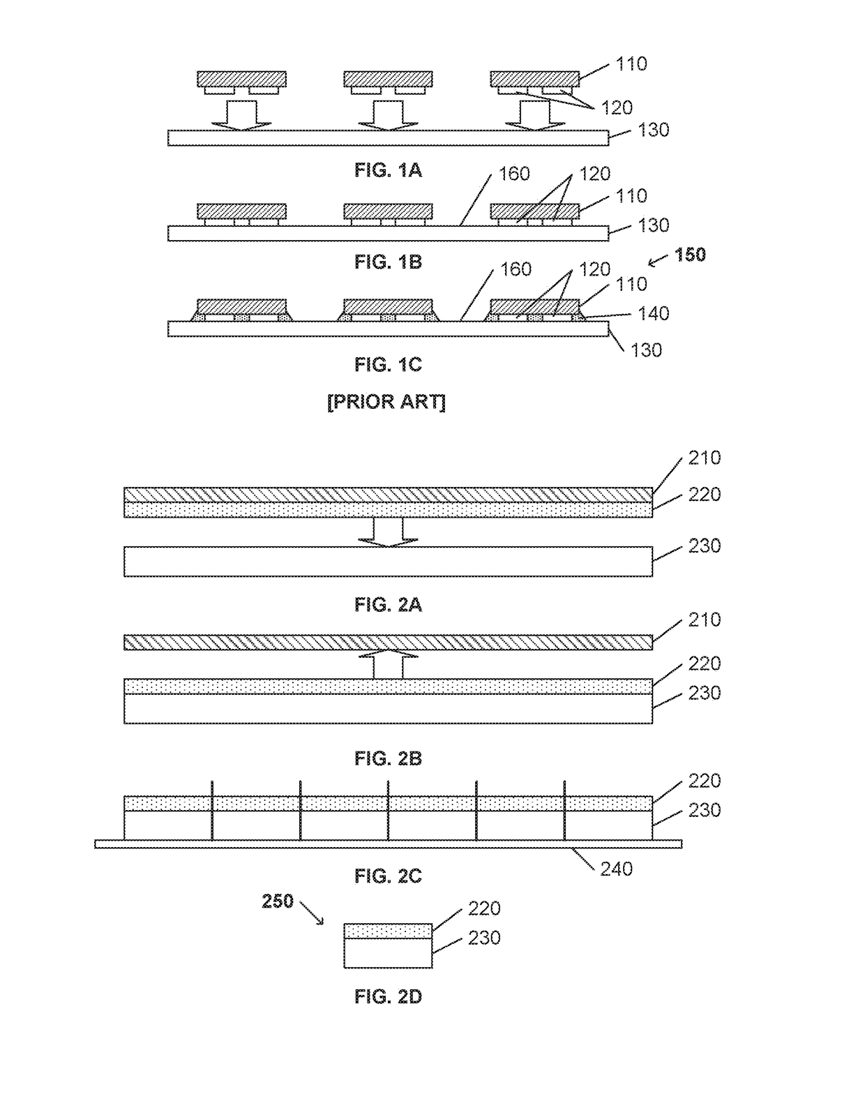
[0019]FIGS. 1A-1C illustrate an example production of light emitting elements 110 on a substrate 130. The light emitting elements 110 may be any...


PUM


Abstract

A multi-stage lamination process is used to laminate a wavelength conversion film (220) to a transparent substrate (230), and subsequently to a light emitting element (110). The wavelength conversion film (220) may be an uncured phosphor-embedded silicone polymer, and the lamination process includes heating the polymer so that it adheres to the transparent substrate (230), but is not fully cured. The phosphor-laminated transparent substrate (230) is sliced / diced and the wavelength conversion film (220) of each diced substrate is placed upon each light emitting element (110). The semi-cured wavelength conversion film (220) is then laminated to the light emitting element (110) via heating, consequently curing the phosphor film. Throughout the process, no glue is used, and the optical losses associated with glue material are not introduced.

Description

FIELD OF THE INVENTION[0001]This invention relates to the field of light emitting devices, and in particular to light emitting devices that include a phosphor converter and does not use glue to adhere the elements together.BACKGROUND OF THE INVENTION[0002]The ever expanding use of semiconductor light emitting devices has produced a highly competitive market for these devices. In this market, performance and price are often significant for providing product distinction among vendors. Decreasing optical losses, and consequently increasing light output efficiency, provides improved performance, as does improving optical quality. If the process used to decrease the optical losses and / or improve the optical quality can be performed with lesser manufacturing costs, the performance to price ratio may increase dramatically.[0003]Conventional light emitting devices typically include a number of discrete elements that are used to produce light of a desired color with a desired light output pa...

Claims


Application Information

Patent Timeline
IPC IPC(8): H01L33/50H01L33/60H01L33/00
CPCH01L33/505H01L33/0095H01L33/60H01L33/58H01L2933/0041H01L2933/0058H01L33/005H01L33/44H01L33/501H01L2924/12041
Inventor BASIN, GRIGORIYMARTIN, PAULCHOI, HAN HO
Owner LUMILEDS
Learn More