
Combined pitch and forward thrust control for unmanned aircraft systems

a technology of unmanned aircraft and combined thrust control, which is applied in the direction of vehicle position/course/altitude control, process and machine control, instruments, etc., can solve the problems of reducing the reliability of small engines used in various unmanned aircraft systems (uas), adding further drag to the aircraft, and not providing adequate control of the aircraft during hovering

Active Publication Date: 2017-10-19
L3HARRIS UNMANNED SYST INC
View PDF3 Cites 43 Cited by
  • Summary
  • Abstract
  • Description
  • Claims
  • Application Information

AI Technical Summary

Benefits of technology

This patent is for an unmanned aircraft system that includes a forward thrust engine and a first rotor, along with a vertical thrust engine and a second rotor. The system also includes a pitch angle and throttle control system that receives a pitch angle command and generates a reduced pitch angle command to prevent the aircraft from exceeding a certain angle. The system also includes a processor that combines the reduced pitch angle command with a forward thrust engine throttle command to achieve efficient and safe operation of the aircraft.

Problems solved by technology

However, the small engines used in various Unmanned Aircraft Systems (UAS) have demonstrated a lower reliability as compared to piloted aviation engines.
While this may be acceptable for non-fixed-wing aircraft, it is undesirable in hybrid multirotor aircraft because a negative angle of attack of the fixed wing under conditions of more than minimal airspeed would cause a downward force on the aircraft.
This would require the VTOL propulsion system to provide additional thrust to maintain altitude and would add further drag to the aircraft.
This scheme, however, does not provide adequate control of the aircraft during hovering modes in which a non-trivial airspeed is required, such as hovering in windy conditions.
With such configurations, however, the integrators may end up fighting each other to achieve stable control, but at a reduced efficiency.
For example, a large pitch up command combined with a large forward thrust may result in stable position control, but both systems are working harder than desired.

Method used


Image

  • Combined pitch and forward thrust control for unmanned aircraft systems
  • Combined pitch and forward thrust control for unmanned aircraft systems
  • Combined pitch and forward thrust control for unmanned aircraft systems

Examples


Embodiment Construction

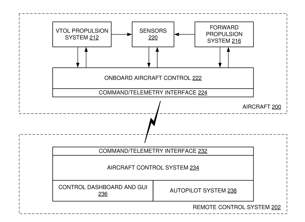
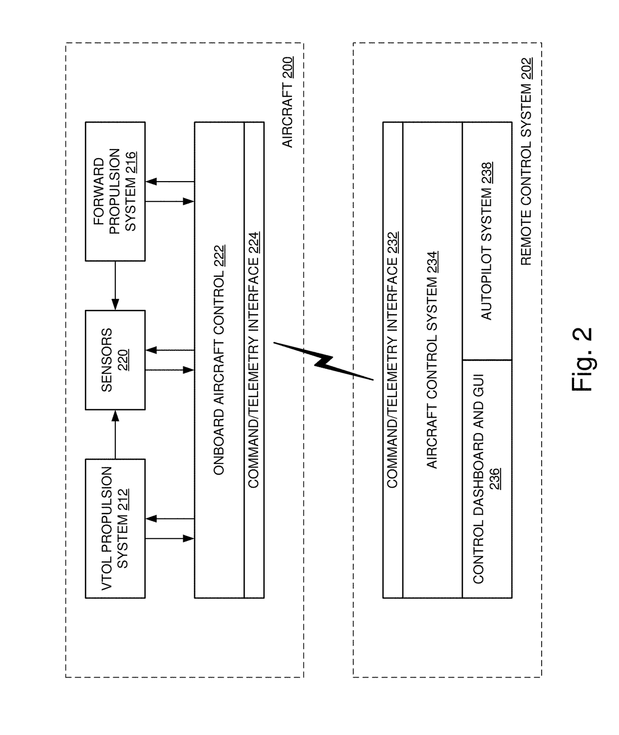
[0007]According to various embodiments of the disclosed technology systems and methods for pitch angle forward thrust of an aircraft is combined with forward thrust of the main fixed-wing engine or engines to allow control of forward velocity of the aircraft. In some embodiments, this can be implemented so as to allow the aircraft remain level in hovering flight across a wide range of air speeds.

[0008]According to an embodiment of the disclosed technology, an unmanned aircraft may include: a forward propulsion system comprising a forward thrust engine and a first rotor coupled to the forward thrust engine; a vertical propulsion system that includes a vertical thrust engine and a second rotor coupled to the vertical thrust engine; and a pitch angle and throttle control system. The pitch angle and throttle control system may include: a controller comprising an input coupled to receive a velocity signal indicating a determined amount of forward velocity and being configured to generate...


PUM


Abstract

An unmanned aircraft includes a forward propulsion system comprising one or more forward thrust engines and one or more corresponding rotors coupled to the forward thrust engines; a vertical propulsion system comprising one or more vertical thrust engines and one or more corresponding rotors coupled to the vertical thrust engines; and a pitch angle and throttle control system, comprising a processor configured to receive a first pitch angle command; and generate a second pitch angle command and a forward thrust engine throttle command based on a bounded pitch angle for the aircraft.

Description

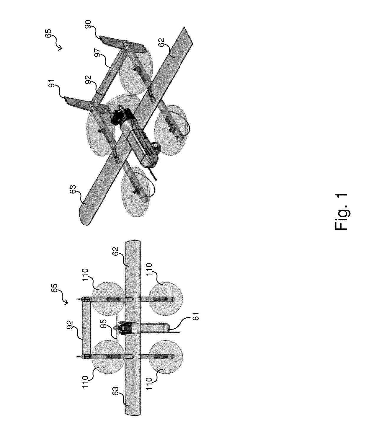
TECHNICAL FIELD[0001]The disclosed technology relates generally to aircraft control systems, and more particularly, some embodiments relate to combining forward thrust control of a multirotor vertical propulsion system with thrust control of the forward propulsion system to control the aircraft in hovering flight across a wide range of air speeds.DESCRIPTION OF THE RELATED ART[0002]Unmanned aircraft have become ubiquitous in today's society. Their importance and value has grown dramatically in recent years, leading to widespread adoption in commercial, military and consumer market sectors. Part of the reason for their popularity is their low cost and small form factor as compared to piloted aircraft. However, the small engines used in various Unmanned Aircraft Systems (UAS) have demonstrated a lower reliability as compared to piloted aviation engines.[0003]Hybrid aircraft use a combination of vertical takeoff and landing (VTOL) propulsion systems to allow the aircraft to take off an...

Claims


Application Information

Patent Timeline
IPC IPC(8): G05D1/08G05D1/00B64C29/00B64C39/02
CPCG05D1/0858B64C39/024B64C29/0025B64C2201/104B64C2201/146B64C2201/108G05D1/0011B64U70/80B64U30/10B64U2201/00B64U50/18B64U30/29B64U50/11B64U10/20B64U2201/20
Inventor DOUGLAS, JASON MICHAEL K.ARMER, JUSTINMURPHY, CARLOS
Owner L3HARRIS UNMANNED SYST INC
Learn More