
Fluid flow energy extraction system and method related thereto

a fluid flow energy extraction and flow technology, applied in the field of energy extraction, can solve the problems of unfavorable aesthetic appeal of wind energy systems, unfavorable environmental protection, and high material cost, and achieve the effects of reducing noise pollution, wildlife threat, and low cost of materials

Active Publication Date: 2017-10-19
TEXAS TECH UNIV SYST
View PDF8 Cites 2 Cited by
  • Summary
  • Abstract
  • Description
  • Claims
  • Application Information

AI Technical Summary

Benefits of technology

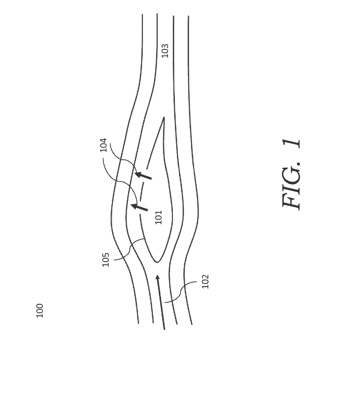
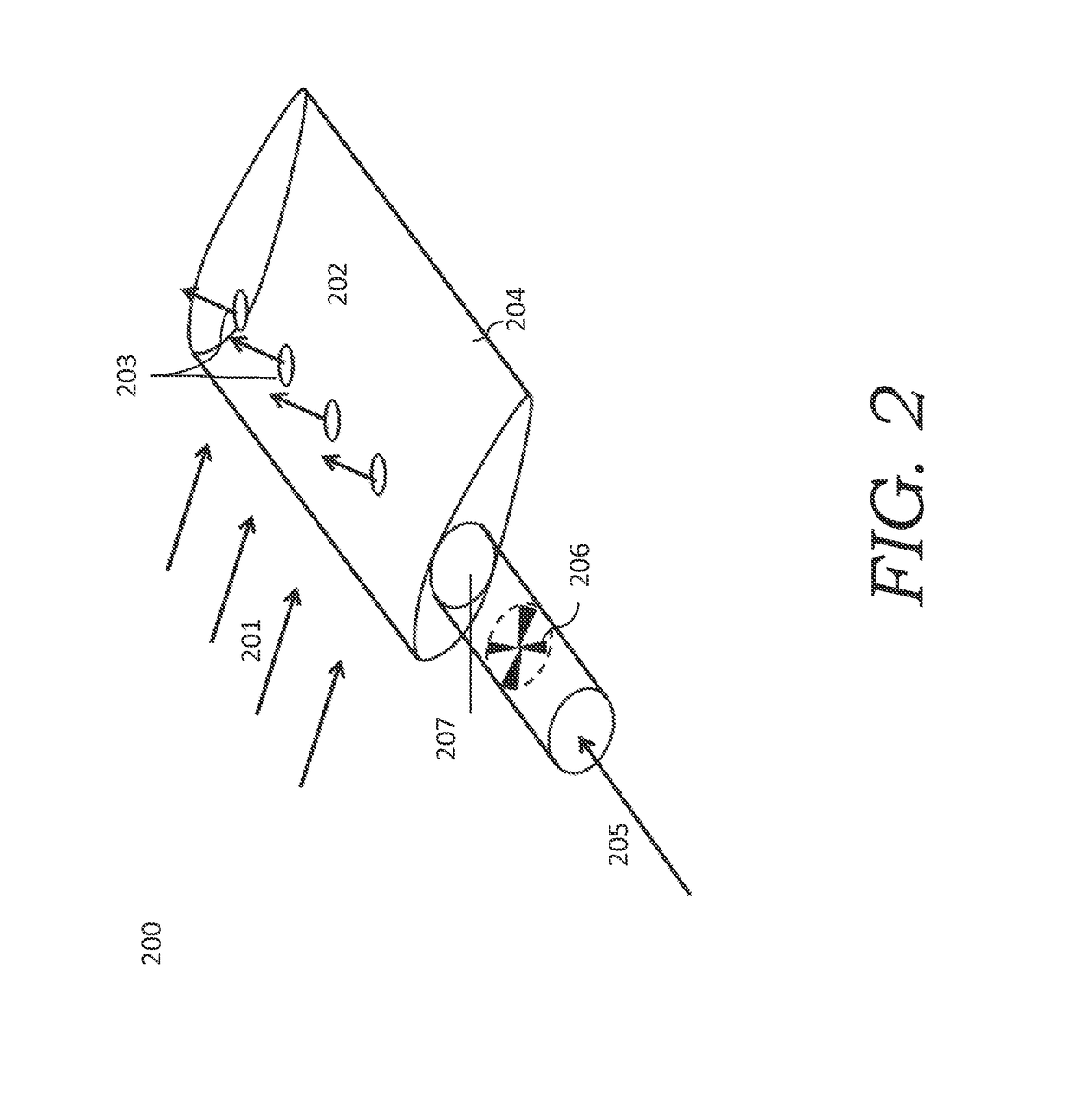
The present invention addresses the limitations of current technology by creating a high pressure potential in a passive structure. This can be achieved through the use of aerodynamic assemblies, such as airfoils, which are designed to maximize the generation of high pressure potential. The invention also involves the placement of orifices or slits along the surface of the blade to enhance the airfoil performance. The invention can be used in various applications, such as wind energy, to achieve higher efficiency and reduce noise pollution and land mass use. The invention effectively and economically places all the relevant heavy machinery at the ground level of the disclosed embodiments.

Problems solved by technology

However, the large mass of machinery required in wind energy systems results in a high cost of materials.
Also, the placement of the machinery at such a height results in tedious and expensive maintenance.
Additionally, the noise pollution, potential wildlife threat, land mass use, and lack of aesthetic appeal associated with wind energy systems can be unfavorable.
This adds weight to the top of the system and imposes a relatively high materials usage in the machinery, tower and foundation.
Furthermore, the large rotors are fragile systems, which need to be made from high performance composites.
Their rotation can have a number of unintended side effects such as interaction with wild life, throwing ice accumulation, lightning attraction and many other issues.
In addition the maintenance of the system is difficult as it has to be done at height.
These types of problems become more significant when turbines are installed close to population centers or directly on buildings.
Conventional or unconventional water flow extraction systems (tidal, river or similar systems) in the renewable energy fields pose very similar sets of problems.
The performance drawback comparing this concept to a modern day wind turbine is obviously that there are a series of losses associated with the system.
Although very attractive, the concept has the same drawbacks as conventional wind turbines.
Further, the structure has to carry aerodynamic loading from the shroud.
Despite efforts to create more efficient and reliable flow energy extraction systems, there are currently no commercially successful approaches which limit many of the inherent risks and drawbacks of the traditional turbine design.

Method used


Image

  • Fluid flow energy extraction system and method related thereto
  • Fluid flow energy extraction system and method related thereto
  • Fluid flow energy extraction system and method related thereto

Examples


example

[0075]Computational fluid dynamics (CFD) results have been used to calculate different configurations. FIG. 15 shows a two dimensional version of such calculation. The airfoils are inserted into a large computational domain in order to avoid blockage, as such would artificially increase the performance of the device in the calculations, such as normally done when investigating energy extraction devices (wind turbines). Flow is injected from the hollow of the airfoils. Different configurations of orifice size, location and airfoil configuration have been investigated using this particular calculation method such as outlined in the technology description.

[0076]The results of two configurations is shown in FIG. 16A-B, where the power extracted in Watt-per-meter airfoil and the corresponding power coefficient has been calculated as a function of the pressure differential between the hollow of the airfoils and the ambient pressure. This pressure differential is controlled by the energy e...


PUM


Abstract

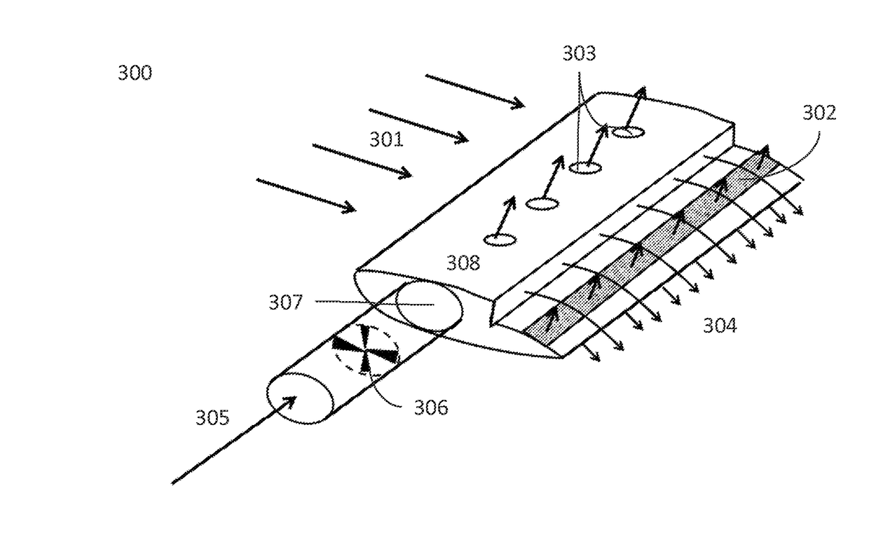
Disclosed is a system and method for both consumer and utility scale energy extraction from flow-based energy sources. The passive system may utilize directing perforations on a surface in order to create and air jet vortex generators. Alternatively the system may provide for flow through discrete orifices aligned with the span of an aerodynamic assembly in a co-flow direction, utilizing a Coanda effect. Further additional configurations include directing flow through a perforated surface skin that is near the trailing edge on the suction side. Even further are embodiments for blowing air directly out of the trailing edge of an airfoil. The disclosed systems and methods support a wide variety of scenarios for fluid flow energy extraction, such as wind or water flow, as well as for related products and services.

Description

CROSS-REFERENCE TO RELATED APPLICATIONS[0001]This application is a national phase filing of PCT / US2015 / 053002, filed on Sep. 29, 2015, entitled “Fluid Flow Energy Extraction System and Method Related Thereto” which claims priority to provisional U.S. Patent Application Ser. No. 62 / 057,325, filed on Sep. 30, 2014, entitled “Fluid Flow Energy Extraction Systems and Methods Related Thereto” which such applications are commonly assigned to the Assignee of the present invention and which disclosures are hereby incorporated herein by reference in their entirety for all purposes.[0002]This application includes material that is subject to copyright protection. The copyright owner has no objection to the facsimile reproduction by anyone of the patent disclosure, as it appears in the World Intellectual Property Office or United States Patent and Trademark Office files or records, but otherwise reserves all copyright rights whatsoever.TECHNICAL FIELD[0003]The present invention relates in gener...

Claims


Application Information

Patent Timeline
Patent Type & Authority Applications(United States)
IPC IPC(8): F03D3/04F03D9/34F03D9/25F03B13/10F03D9/28
CPCF03D3/04F03D9/25F03D9/28F05B2240/9112F03B13/10F05B2240/133F03D9/34F03D1/04Y02B10/30Y02E10/728Y02E10/74F03D9/20Y02E10/20Y02E10/72
Inventor WESTERGAARD, CARSTEN HEIN
Owner TEXAS TECH UNIV SYST
Learn More