
Filter cup

Active Publication Date: 2017-10-19
LIN TSAI HUI
View PDF9 Cites 4 Cited by
  • Summary
  • Abstract
  • Description
  • Claims
  • Application Information

AI Technical Summary

Benefits of technology

The present invention provides a filter cup that is easy and convenient to use by an inner cup mounted in an outer cup and pushed to move upward for allowing liquid therein flowing out smoothly. The filter cup has a bottom side with a conical surface that forms a filter bottom surface, with a plug-like member arranged at the filter bottom surface. The inner cup has flanges on its edges. The outer cup mounts the inner cup, with a discharge hole plugged by a plug-like member to prevent liquid in the inner cup from leaking out. The user only needs to pull the grip to a certain position and then the inner cup is moved upward, with the liquid in the inner cup flowing out through the gap between the plug-like member and the discharge hole. The user doesn't need to apply force to the grip continuously.

Problems solved by technology

However, these prior arts all require the external force applied continuously to filter the tea infusion and make the tea infusion flow out.
This causes inconvenience in use.

Method used


Image

  • Filter cup
  • Filter cup
  • Filter cup

Examples


Embodiment Construction

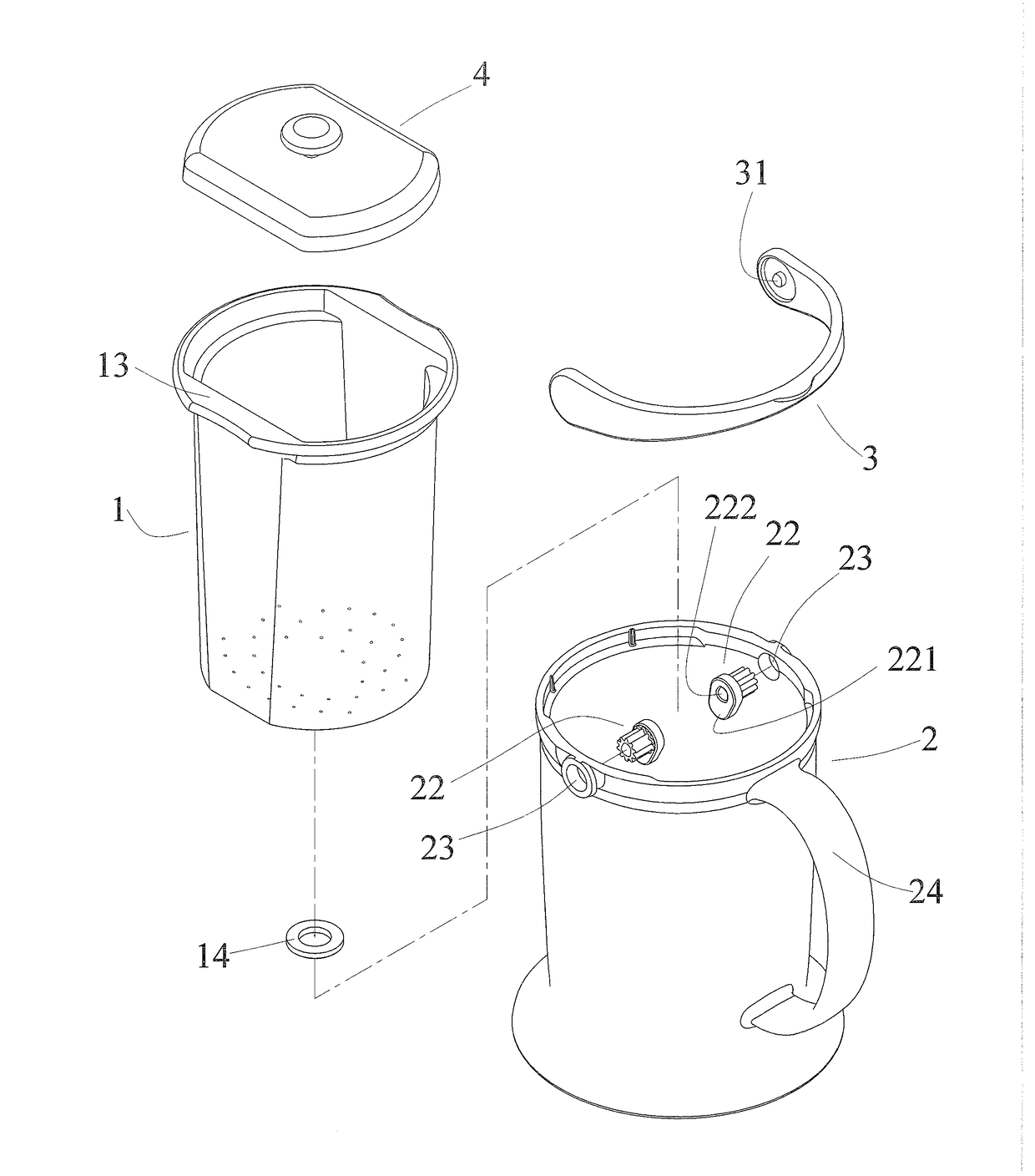
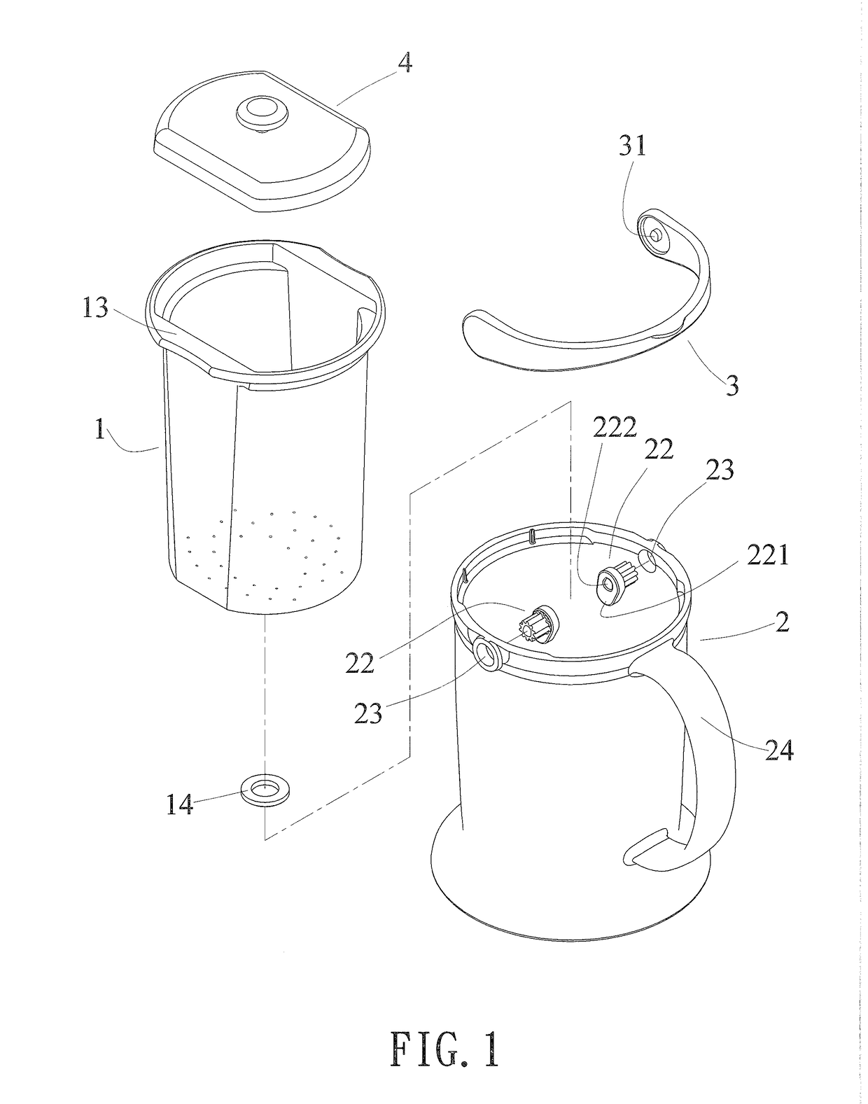
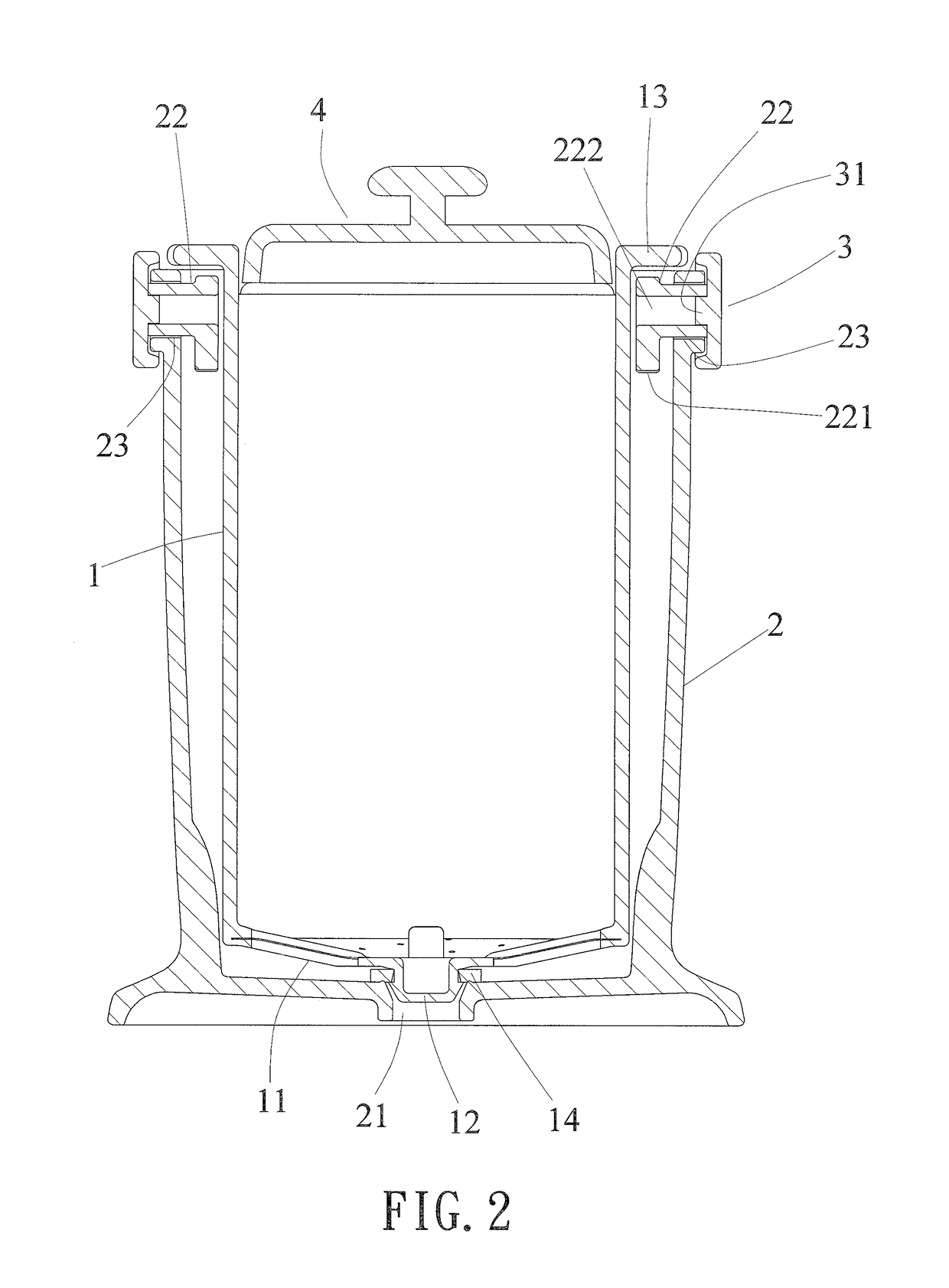
[0027]Refer to FIG. 1, FIG. 2 and FIG. 3, a filter cup of the present invention mainly includes an inner cup 1, an outer cup 2 and a grip 3.

[0028]A bottom side of the inner cup 1 is a conical surface used as a filter bottom surface 11. A plug-like member 12 is set on the filter bottom surface 11. At least two flanges 13 are formed on two corresponding edges of the top of the inner cup 1. In a preferred embodiment of the present invention, the filter bottom surface 11 is a filter screen. The inner cup 1 further includes a sealing gasket 14 arranged around the plug-like member 12.

[0029]The inner cup 1 is mounted in the outer cup 2. A discharge hole 21 is disposed on the bottom surface of the outer cup 2 and is corresponding to the plug-like member 12 of the inner cup 1. The plug-like member 12 is plugged into and closely matched with the discharge hole 21 to prevent liquid in the inner cup 1 from leaking out. Two rotating members 22 are pivotally connected to an upper part of the oute...


PUM


Abstract

A filter cup is revealed. The filter cup includes an outer cup, an inner cup mounted in the outer cup and a grip. The inner cup consists of a filter bottom surface on the bottom thereof, a plug-like member on the filter bottom surface, and at least two flanges on top of the inner cup. A discharge hole is disposed on bottom of the outer cup and sealed by the plug-like member. Two rotating members are pivotally connected to the outer cup and each includes a leaning portion projecting therefrom. The grip is connected to the rotating members. The rotating members are driven to move for pushing the flanges and moving the inner cup vertically by the leaning portions thereof when the grip is pulled. Thus a gap is formed between the plug-like member and the discharge hole, allowing liquid in the inner to flow out therethrough.

Description

BACKGROUND OF THE INVENTIONField of the invention[0001]The present invention relates to a filter cup, especially to a filter cup that includes an outer cap and an inner cup mounted in the outer cap. A gap is generated between the inner and the outer cups through the inner cup being pushed to move upward. Thus residue is left in the inner cup while infusion is passed through the gap and a discharge hole of the outer cup to be discharged.Descriptions of Related Art[0002]In order to prevent tea or fruit from being soaked in a teapot too long and the infusion may have astringent or sour taste, the infusion and the residue of tea or fruit should be separated after a period of time. Thus users can drink the infusion directly while the separated residue of tea or fruit can be soaked again.[0003]Refer to Taiwanese Utility Model Pat. No. M385994 U, a filter cup is disclosed. The filter cup includes a cup body mounted in an outer housing. The cup body is disposed with a hole communicating wit...

Claims


Application Information

Patent Timeline
IPC IPC(8): A47J31/06A47G19/22
CPCA47G19/22A47J31/0615A47G19/14
Inventor LIN, TSAI-HUI
Owner LIN TSAI HUI
Learn More