
Electrical receptacle connector

Active Publication Date: 2017-10-12
ADVANCED CONNECTEK INC
View PDF0 Cites 4 Cited by
  • Summary
  • Abstract
  • Description
  • Claims
  • Application Information

AI Technical Summary

Benefits of technology

The patent text describes a new design for an electrical receptacle connector that has a double-layer shell structure formed by an inner shell and an outer shell. The inner shell is designed to improve its strength around the insertion opening, preventing deformation or bending when an electrical plug connector is inserted. The connector also has improved fixation with the circuit board and reduces the cost for fabricating the holes of the circuit board. The design also includes features to prevent solder wicking and enhance the overall performance of the connector.

Problems solved by technology

However, in the conventional, the structural strength at the insertion opening of the outer iron shell is insufficient, and the outer iron shell is devoid of additional structural enhancing units.
As a result, when an electrical plug connector is inserted into the insertion opening of the outer iron shell, the insertion opening of the outer iron shell may deform or bend.
Therefore, how to solve the aforementioned problem is an issue.

Method used


Image

  • Electrical receptacle connector
  • Electrical receptacle connector
  • Electrical receptacle connector

Examples


Embodiment Construction

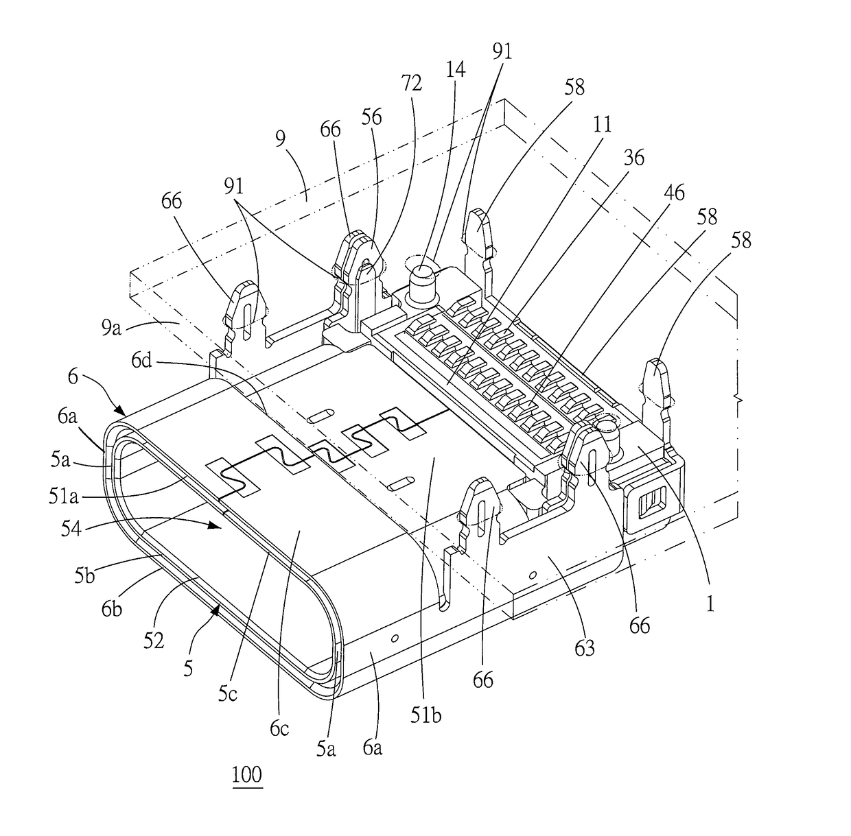
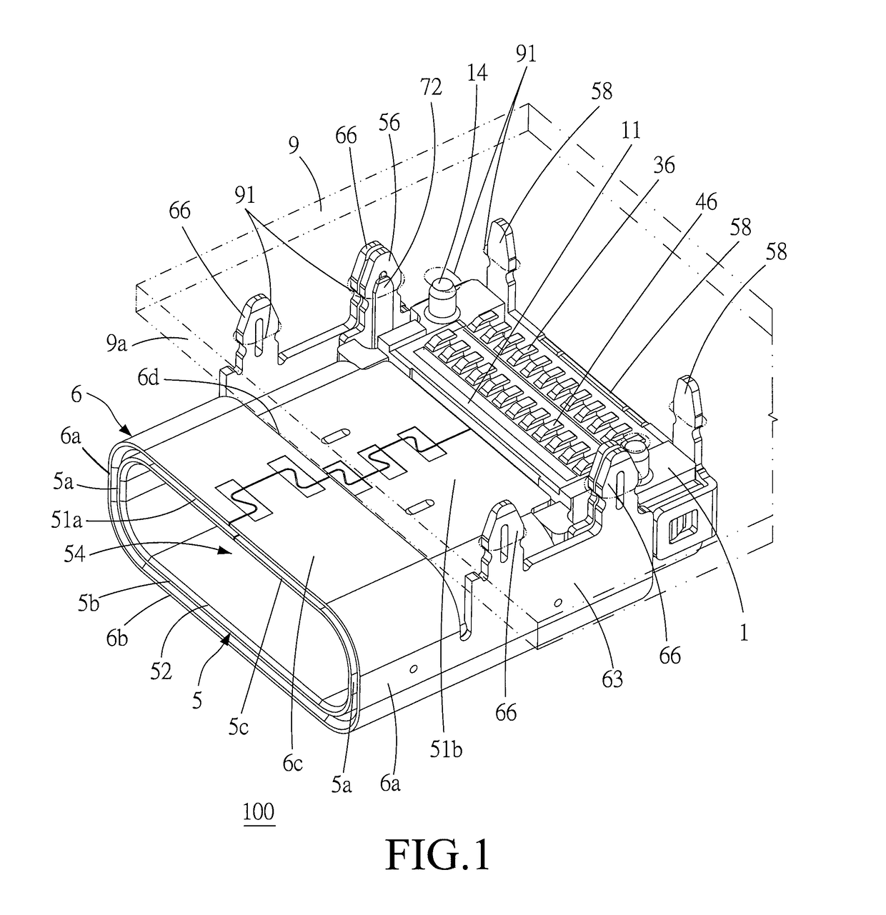
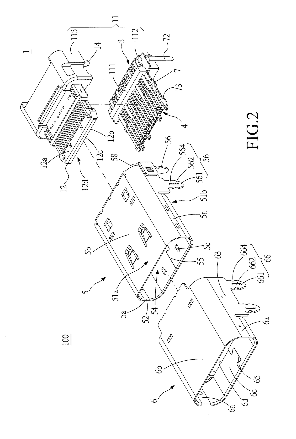
[0032]Please refer to FIGS. 1 to 4, illustrating an electrical receptacle connector of an exemplary embodiment of the instant disclosure. FIG. 1 illustrates a perspective view of the electrical receptacle connector mounted onto a circuit board. FIG. 2 illustrates an exploded view of the electrical receptacle connector. FIG. 3 illustrates an exploded view of a terminal module of the electrical receptacle connector. FIG. 4 illustrates a front sectional view of the electrical receptacle connector. In this embodiment, the electrical receptacle connector 100 can provide a reversible or dual orientation USB Type-C connector interface and pin assignments, i.e., a USB Type-C receptacle connector. In this embodiment, the number of the receptacle terminals of the electrical receptacle connector 100 is suitable for USB 3.0 signal transmission, but embodiments are not limited thereto. In one embodiment, the number of the receptacle terminals of the electrical receptacle connector 100 is suitabl...


PUM


Abstract

An electrical receptacle connector includes an inner shell, a terminal module in the inner shell, and an outer shell out of the inner shell. Two side plates, a top plate, and a bottom plate of the inner shell are connected with each other to faun an insertion opening, and the insertion opening is near one end of the inner shell. The outer shell is out of the inner shell and near the insertion opening of the inner shell. The outer shell stacks on the two side plates, the top plate, and the bottom plate of the inner shell to form a double-layer shell structure. Accordingly, the structural strength around the insertion opening of the inner shell can be improved. Hence, when a plug connector is inserted into the insertion opening of the inner shell, the inner shell does not deform or bend easily.

Description

CROSS-REFERENCE TO RELATED APPLICATION[0001]This non-provisional application claims priority under 35 U.S.C. § 119(a) to Patent Application No. 201610219691.3 filed in China, P.R.C. on Apr. 11, 2016, the entire contents of which are hereby incorporated by reference.FIELD OF THE INVENTION[0002]The instant disclosure relates to an electrical connector, and more particular to an electrical receptacle connector.[0003]BACKGROUND[0004]Generally, Universal Serial Bus (USB) is a serial bus standard to the PC architecture with a focus on computer interface, consumer and productivity applications. The existing Universal Serial Bus (USB) interconnects have the attributes of plug-and-play and ease of use by end users. Now, as technology innovation marches forward, new kinds of devices, media formats and large inexpensive storage are converging. They require significantly more bus bandwidth to maintain the interactive experience that users have come to expect. In addition, the demand of a higher...

Claims


Application Information

Patent Timeline
IPC IPC(8): H01R12/71H01R24/64H01R13/6581H01R13/502
CPCH01R12/716H01R13/502H01R2107/00H01R13/6581H01R24/64H01R4/028H01R12/58H01R13/02H01R13/516H01R13/6585H01R13/73H01R13/6593
Inventor TSAI, YU-LUNHOU, PIN-YUANLIAO, CHUNG-FUCHEN, LONG-FEICHEN, HUNG-YUWANG, HSU-FEN
Owner ADVANCED CONNECTEK INC
Learn More