Artificially expanding the tide range of a tidal barrage

Inactive Publication Date: 2017-10-05
WATKINS DANIEL ROBERT
View PDF2 Cites 0 Cited by
  • Summary
  • Abstract
  • Description
  • Claims
  • Application Information

AI Technical Summary

Benefits of technology

[0004]Hydroelectric power using tidal barrages has been capping out, as there are a limited number of planet geographies where these are economically feasi...

Problems solved by technology

Hydroelectric power using tidal barrages has been capping out, as there a...

Method used


Image

  • Artificially expanding the tide range of a tidal barrage
  • Artificially expanding the tide range of a tidal barrage
  • Artificially expanding the tide range of a tidal barrage

Examples


Embodiment Construction

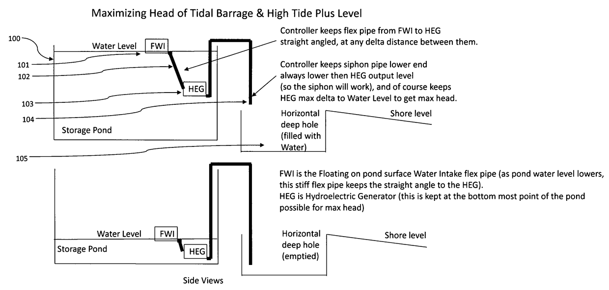
[0027]FIG. 1, illustrates two side view examples, of the tidal barrage. The embodiments described herein are not limited to this example. The water storage pond 100 has a flat bottom, sides and a water level that reflects the high tide mark plus more height (referred to has High Tide Plus Level, or HTPL), provided by system features. The FWI (Floating on the pond surface Water Intake flex pipe) 101 provides the water to the flex pipe 102 that provides the water to the HEG (Hydroelectric Generator) 103 input. Siphon pipe 104 takes the HEG output water and siphons it out of the pond. The shore hole 105 is used to provide below low tide level to the siphon so the pond can be even deeper with water (which then provides more tidal range).

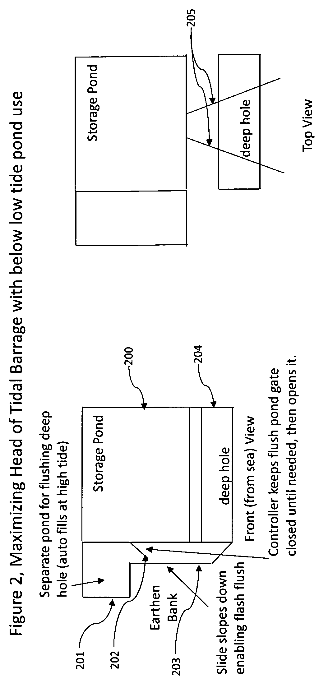
[0028]FIG. 2, illustrates a front view and a top view example, of the tidal barrage. The embodiments described herein are not limited to this example. The flushing pond 201 provides water storage for use in flushing shore holes. The flushing pond gate 20...


PUM


Abstract

Some geographies have tide ranges above 15 yards, but most do not. The wider the tide range, the more hydroelectric power can be generated per cycle of low tide to high tide and then high tide to low tide, using a tidal barrage. Methods of raising the high tide above the measured level to fill the storage ponds to an even higher level and a method to empty the storage ponds to a lower than low tide level, provide means to expand the tide range significantly, enabling many more planet geographies to have economically feasible hydroelectric power.

Description

BACKGROUND OF THE INVENTION[0001]The invention pertains to expanding of tide range of tidal barrages, using enhancements to water storage ponds, methods to raise above high tide levels water that fills the ponds, a method to lower the lowest point at which water can be used in the ponds, and controlling the system to have maximum head available always for water flow use in hydroelectric generation.DESCRIPTION1. Field of the Invention[0002]The invention relates to the field of expanding the tide range of a tidal barrage while maximizing the head available, for hydroelectric generation.2. Prior Art[0003]Regarding filling the storage pond above the high tide level, some systems with turbines use excess energy in the grid to power the turbines in reverse which will pump water in to the storage pond at high tide to raise the level, typically a few feet. The downside is this costs energy to pump this water and the amount of feet added to the pond level is limited.SUMMARY OF THE INVENTION[...

Claims


Application Information

Patent Timeline
IPC IPC(8): F03B13/26F03B13/14H02K7/18
CPCF03B13/268F03B13/147H02K7/1823F03B13/086Y02E10/30
Inventor WATKINS, DANIEL ROBERT
Owner WATKINS DANIEL ROBERT
Why Eureka
Try Eureka