
Circuit for controlling and identifying a plasma torch

a plasma torch and circuit technology, applied in the direction of plasma welding equipment, electrical equipment, arc welding equipment, etc., can solve the problems of disturbing the reading and management of the torch by the equipment, breaking the wires,

Inactive Publication Date: 2017-10-05
POWERMIG AUTOMACAO E SOLDAGEM
View PDF2 Cites 6 Cited by
  • Summary
  • Abstract
  • Description
  • Claims
  • Application Information

AI Technical Summary

Benefits of technology

The present invention describes an electronic circuit that enables monitoring and control of a device's actions without the need for multiple cables. The circuit centralizes the activation information for the pilot arc of the torch, controls the torch mouth, and identifies the torch model. It also manages communications between the cutting supply and the torch using just two connection wires with the device. This ensures longer working life of the equipment and reduces excessive stops during operation. The circuit allows the torch to operate with power between 20 A and 400 A.

Problems solved by technology

Therefore, the wires coming from the plasma torch promoting the activation of the guiding arc, the safety of the mouth system and the identification of the power of the torch are currently linked and managed by the equipment usually located at a distance of up to 10 meters from the plasma torch, frequently breaking the wires and disturbing the reading and management of the torch by the equipment.
Such equipment, besides having various command wires, have a maximum energy source transmission capability of 80 A, thus restricting its use, besides causing various stops due to wire breaking by equipment overload.

Method used


Image

  • Circuit for controlling and identifying a plasma torch
  • Circuit for controlling and identifying a plasma torch
  • Circuit for controlling and identifying a plasma torch

Examples


Embodiment Construction

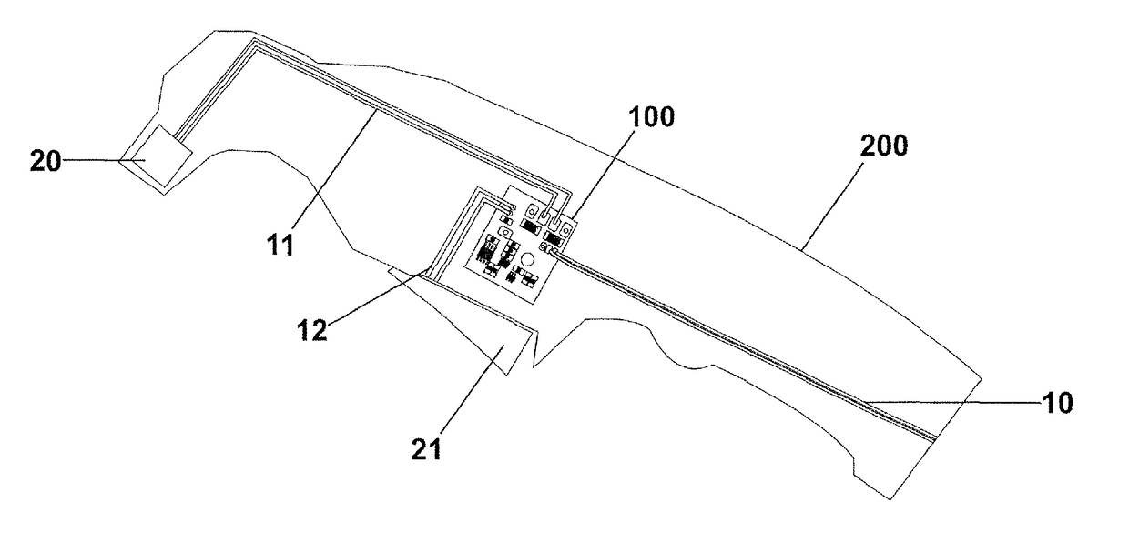
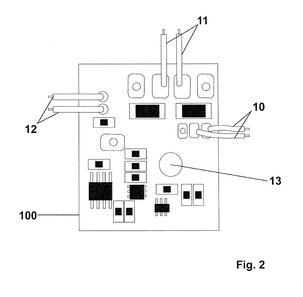
[0012]The circuit for control and identification of a plasma torch object of the present invention discloses an electronic circuit plate (100) provided by a microcontroller located next to the plasma cut torch (200), controlling and identifying the plasma torch (200) next to the central plate (30) of the equipment (300) by means of two wires (10) known as “network” performing communication between the circuit (100) and the power supply of the device (300).

[0013]The electronic circuit plate (100) is provided with a microcontroller promoting the safety control for the mouth (20) of the torch by means of two interlinked wires (11) between the plate (100) and the mouth of the torch (20), said wires (11) also promoting power control of the torch next to the plate (100). Furthermore, the circuit plate (100) performs the control of activation of the trigger (21) of the torch by means of two interlinked wires (12) between the plate (100) and the trigger of the plasma torch (21).

[0014]The in...


PUM


Abstract

A circuit for the control and identification of a plasma torch comprising an electronic circuit plate (100) provided with a microcontroller located next to the plasma cut torch (200), controlling and identifying the plasma torch (200) next to the central plate (30) of the device (300) by means of two wires (10) known as “network” which perform the communication between the circuit (100) and the power supply of the device (300) promoting monitoring and control of all the actions of the device, eliminating the need of various wires, solving the problems of frequent stops of the device due to breaking wires and eliminating difficulties to read the power of the plasma torch (200).

Description

FIELD OF THE INVENTION[0001]The present invention discloses a circuit for the control and identification of a plasma torch. More specifically, it comprises an electronic circuit for monitoring and controlling all the actions of the equipment, eliminating the need of various wires, solving the problems of frequent stops of the device due to breaking wires and difficulties in reading the power of the plasma torch.BACKGROUND OF THE INVENTION[0002]Currently, the cutting system by plasma arch consists of a power supply, a starting circuit for the arc and a torch. These constituents of the system provide electric energy, ionization capacity and the control of the process as required to produce high quality cuts and high productivity with various different materials.[0003]However, the state of the art presents plasma cutting torches provided with various command wires, being two wires intended to activate the guiding arc circuit for the torch by the trigger, by manual or mechanized firing....

Claims


Application Information

Patent Timeline
IPC IPC(8): B23K10/00
CPCB23K10/006B23K9/06H05H1/36
Inventor FOCHESATTO, JUAREZ
Owner POWERMIG AUTOMACAO E SOLDAGEM
Learn More