System and apparatus comprising a multi-sensor catheter for right heart and pulmonary artery catheterization
What is Al technical title?
Al technical title is built by PatSnap Al team. It summarizes the technical point description of the patent document.
a multi-sensor catheter and catheterization technology, which is applied in the direction of sensors, fluid speed measurement using thermal variables, telemetric patient monitoring, etc., can solve the problems of affecting the opening and closing of the heart valve, and affecting the normal operation of the heart. achieve the effect of reducing on
Active Publication Date: 2017-10-05
HEMOCATH LTD
View PDF2 Cites 10 Cited by
Summary
Abstract
Description
Claims
Application Information
AI Technical Summary
This helps you quickly interpret patents by identifying the three key elements:
Problems solved by technology
Method used
Benefits of technology
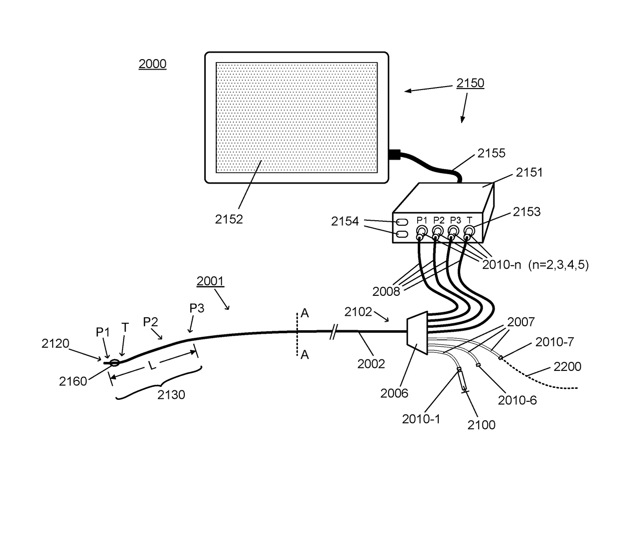
[0025]The present invention seeks to mitigate one or more disadvantages of known systems and apparatus comprising multi-sensor catheters or multi-sensor guidewires for measuring cardiovascular parameters, and in particular to provide systems and apparatus with particular applicability for measurements of hemodynamic parameters during right heart catheterization (RHC) and PA catheterization.
[0028]The multi-sensor catheter may further comprise another lumen having a proximal port and an opening at the distal tip of the catheter tubing, said lumen having a diameter which accepts a guidewire, e.g. a standard 0.025 inch (0.625 mm) guidewire, to enable the catheter to be inserted over the guidewire. For example, to facilitate insertion into the PA, the guidewire is first steered into the RV and PA, and then the catheter is introduced over the guidewire. The latter facilitates introduction of the PA catheter by a more tortuous route, for example when it is introduced from the inferior vena cava.
[0036]Embodiments of the present invention provide improved or alternative guidewire directed catheters and flow directed balloon catheters that enable direct measurements of cardiovascular parameters, including measurement of pressure concurrently within the RA, RV, and PA, during RHC and PA catheterization procedures.
[0043]Thus, apparatus and systems comprising a multi-sensor PA catheter are provided that mitigate one or more problems with known systems and apparatus for RHC and PA catheterization, which allow for diagnostic measurements and monitoring of hemodynamic parameters, including measurement of blood pressure concurrently at multiple locations within the right heart and PA.
Problems solved by technology
During this procedure, there is some risk that repeatedly advancing and pulling-back the catheter for repositioning tip of the catheter for pressure sensing will interfere with, or disrupt, normal operation of the heart, e.g. cause cardiac arrhythmias (such as atrial or ventricular fibrillation), interfere with opening and closing of the heart valves, or risk damage to the heart tissues.
Also, pressure sensing catheters have limited accuracy.
Measurements may be affected by technical limitations such as reflection of the pressure wave at the tip and distortion if the catheter is kinked or sharply bent.
However, electrical pressure sensors of this type have some drawbacks for in vivo applications, where long thin electrical wires are carrying small electrical signals in humid environment, e.g. requirement for electrical isolation of electrical components, significant electrical drift and temperature sensitivity and electrical interference, such as, cross-talk between wires from multiple electrical sensors and from external electromagnetic sources within the operating room.
Method used
Image
Click on the blue label to locate the original text in one second.
Reading with bidirectional positioning of images and text.
Examples
Embodiment Construction
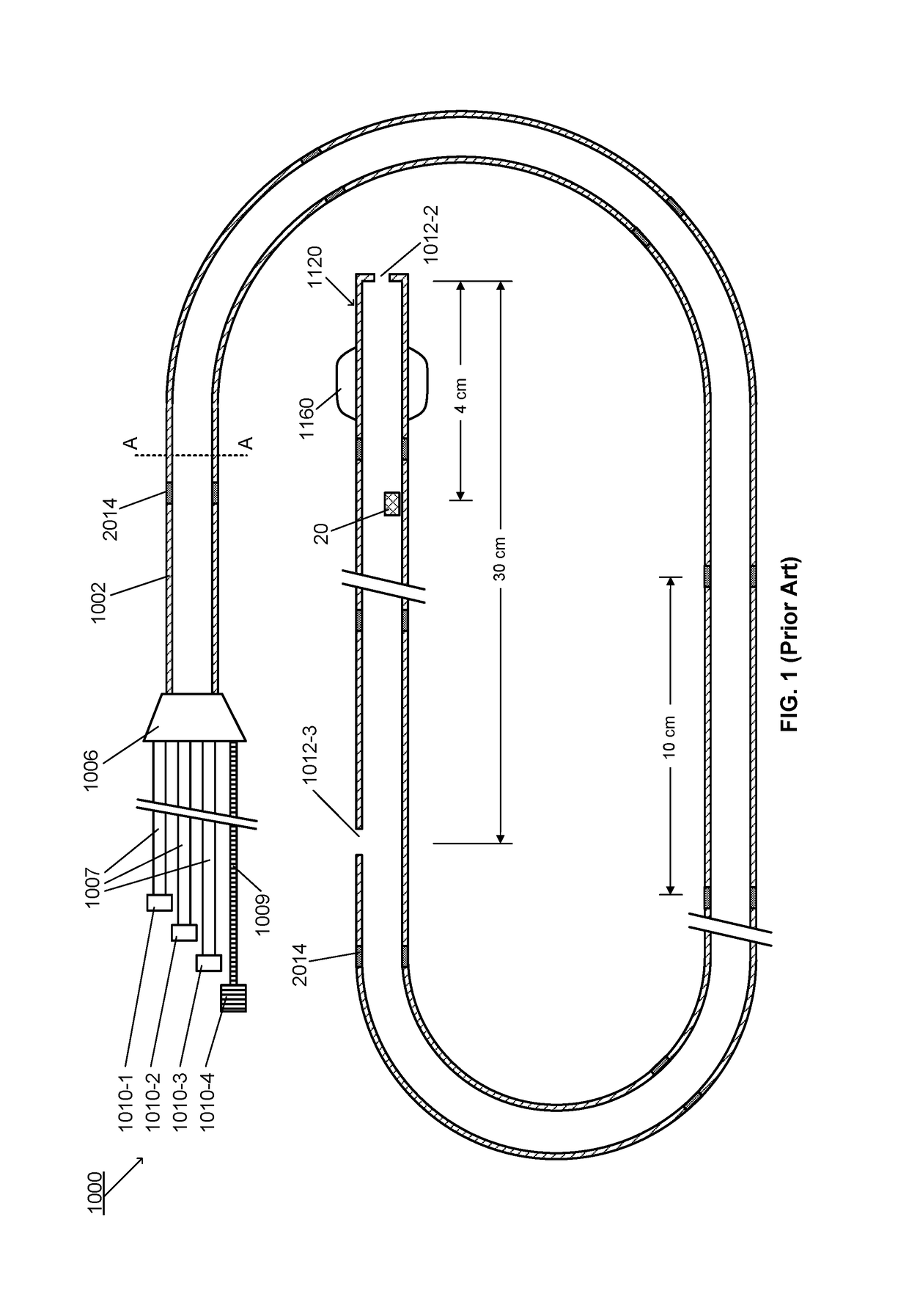
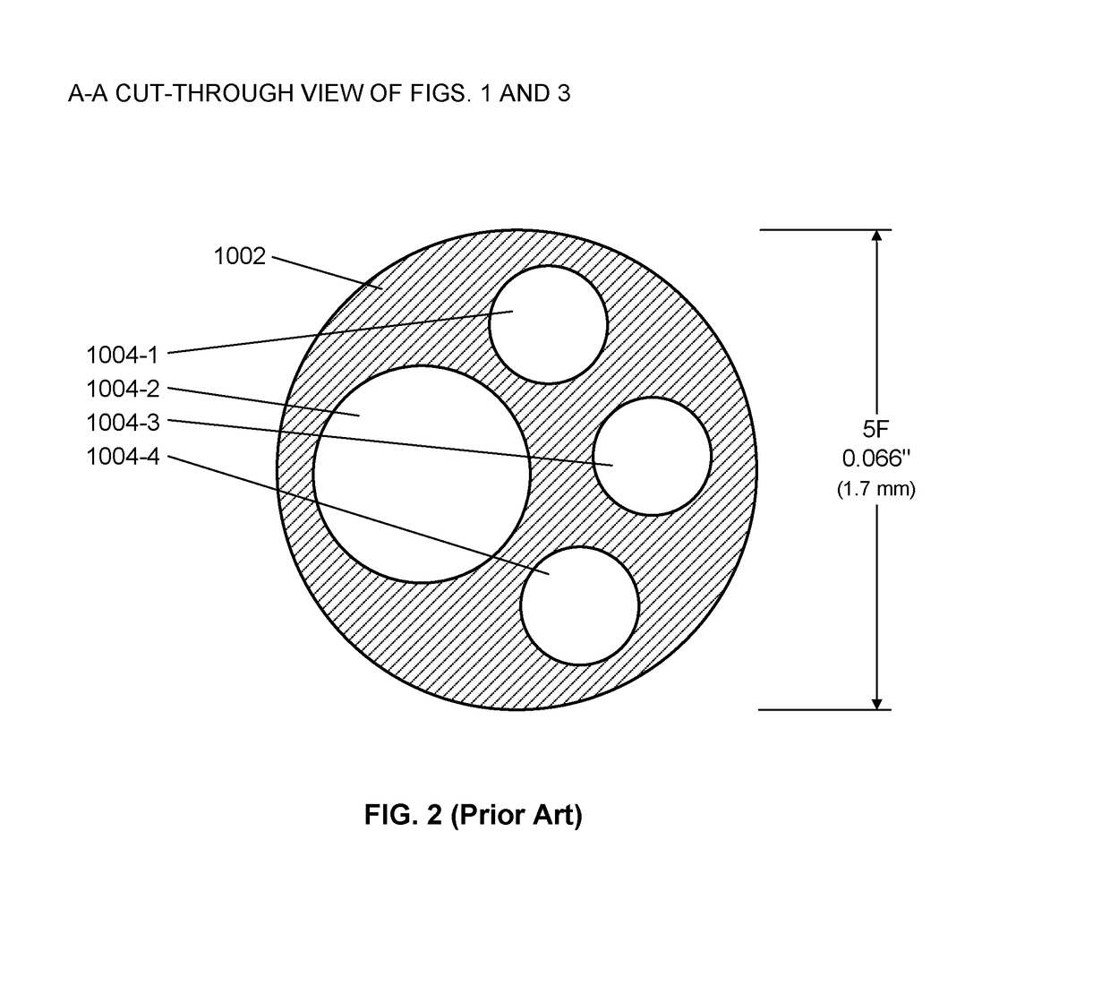
[0061]As illustrated schematically in the longitudinal cross-sectional view shown in FIG. 1, a conventional PA catheter 1000, which may be referred to as a Swan Ganz catheter, comprises a length of multi-lumen catheter tubing 1002 having at its distal end 1120 an inflatable balloon 1160. The catheter typically comprises a multi-lumen catheter tubing 1002, such as illustrated in FIG. 2, which is a cross-sectional view through plane A-A of FIG. 1. By way of example, the catheter tubing shown in FIG. 2 has four lumens 1004-1, 1004-2, 1004-3 and 1004-4, and an outside diameter of 5 French. Referring back to FIG. 1, there is a hub 1006 at the proximal end of the catheter with individual proximal ports 1010-1, 1010-2, 1010-3, and 1010-4. Ports 1010-1, 1010-2, 1010-3 are coupled by individual lengths of flexible tubing 1007 through the hub 1006 to respective lumens 1004-1, 1004-2 and 1004-3 of the catheter tubing 1002. Port 1010-4 is an electrical connector for a thermistor 20 which is loc...
PUM
Abstract
A system and apparatus comprising a multi-sensor catheter for right heart and pulmonary artery catheterization is disclosed. The multi-sensor catheter comprises multi-lumen catheter tubing into which at least three optical pressure sensors, and their respective optical fibers, are inserted. The three optical pressure sensors are arranged within a distal end portion of the catheter, spaced apart lengthwise within the distal end portion for measuring pressure concurrently at each sensor location. The sensor locations are configured for placement of at least one sensor in each of the right atrium, the right ventricle and the pulmonary artery, for concurrent measurement of pressure at each sensor location. The sensor arrangement may further comprise an optical thermo-dilution sensor, and another lumen is provided for fluid injection for thermo-dilution measurements. The catheter may comprise an inflatable balloon tip and a guidewire lumen, and preferably has an outside diameter of 6 French or less.
Description
CROSS-REFERENCE TO RELATED APPLICATIONS[0001]This application is a Continuation-in-Part of U.S. patent application Ser. No. 14 / 874,604, filed Oct. 5, 2015, which is a Continuation of U.S. patent application Ser. No. 14 / 354,624, filed Apr. 28, 2014, which is a national stage entry of PCT International Application No. PCT / IB2012 / 055893, entitled “Apparatus, system and methods for measuring a blood pressure gradient”, filed Oct. 26, 2012, which claims priority from U.S. Provisional patent application No. 61 / 552,778 entitled “Apparatus, system and methods for measuring a blood pressure gradient”, filed Oct. 28, 2011 and from U.S. Provisional patent application No. 61 / 552,787 entitled “Fluid temperature and flow sensor apparatus and system for cardiovascular and other medical applications”, filed Oct. 28, 2011; all these applications are incorporated herein by reference, in their entirety.[0002]This application is a related to U.S. patent application Ser. No. 15 / 001,347, filed Jan. 20, 2...
Claims
Application Information
Patent Timeline
Application Date:The date an application was filed.
Publication Date:The date a patent or application was officially published.
First Publication Date:The earliest publication date of a patent with the same application number.
Issue Date:Publication date of the patent grant document.
PCT Entry Date:The Entry date of PCT National Phase.
Estimated Expiry Date:The statutory expiry date of a patent right according to the Patent Law, and it is the longest term of protection that the patent right can achieve without the termination of the patent right due to other reasons(Term extension factor has been taken into account ).
Invalid Date:Actual expiry date is based on effective date or publication date of legal transaction data of invalid patent.
Patent Type & Authority Applications(United States)