Electrical heating device with PTC element and electrical supply lines as heat conductor and operating fluid tank with such a heating device

Inactive Publication Date: 2017-09-07
ROCHLING AUTOMOTIVE SE
View PDF4 Cites 2 Cited by
  • Summary
  • Abstract
  • Description
  • Claims
  • Application Information

AI Technical Summary

Benefits of technology

The present invention is an electrical heating device that can transfer the most heat to its environment in the shortest time. One way to achieve this is to have multiple PTC elements arranged parallel between the same two electrical conductors. This helps to keep the number of electrical conductors low and allows the surfaces of the conductors to be utilized as heat conducting surfaces. A separate electrical conductor is needed between each two PTC elements in series connection, but this increases the number of heat conductors. The electrical conductors can also be arranged one on top of each other or in a triangular shape to prevent short circuits. Connecting the PTC elements to the electrical conductor can be done using adhesive, soldering, or special fasteners. The device can be covered with a foil or plastic for protection.

Problems solved by technology

This leads to a desired self-limiting of the thermal output of a PTC element.
The chemical stability of the aqueous urea solution that is of interest herein decreases at temperatures higher than 80° C., so that their safe use at high temperatures is highly jeopardized.
It is disadvantageous of the electrical heating device of the above-described type that it requires either a voluminous or complexly configured PTC element with large surface area to quickly heat a correspondingly large volume area in an operating fluid tank.
The heating device may otherwise possibly only be able to selectively input heat for a short time into a tank, which may not be sufficient under certain conditions to quickly achieve the desired degree of reduction in the exhaust after a cold start.

Method used


Image

  • Electrical heating device with PTC element and electrical supply lines as heat conductor and operating fluid tank with such a heating device
  • Electrical heating device with PTC element and electrical supply lines as heat conductor and operating fluid tank with such a heating device
  • Electrical heating device with PTC element and electrical supply lines as heat conductor and operating fluid tank with such a heating device

Examples


Embodiment Construction

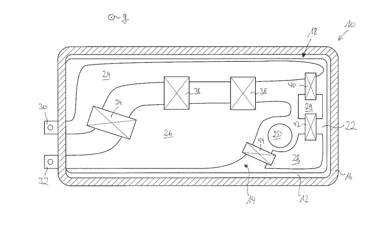
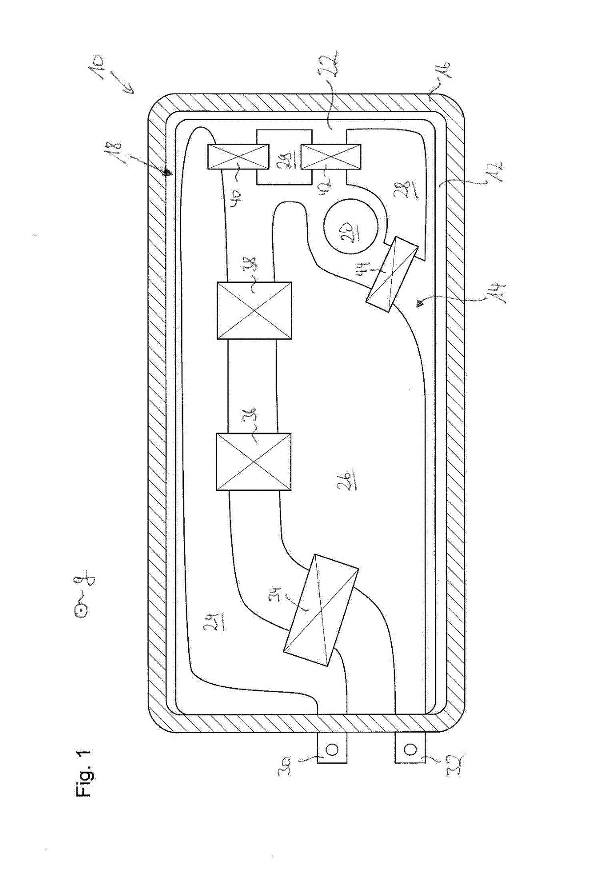
[0043]In the single FIG. 1, a motor vehicle operating fluid tank is identified overall with reference numeral 10. The tank 10 is shown in longitudinal section in a section plane parallel to the bottom. In the finalized operationally ready state arranged in the motor vehicle, the direction of effect of the force of gravity g runs orthogonally to the section plane and orthogonally to the drawing plane of FIG. 1. The section plane passes through a lower case of the tank 10. The observer of FIG. 1 looks thus in the direction of a tank bottom 12, beyond which, that is, in the direction of the observer of FIG. 1, an electrical heating device according to the invention identified overall with reference numeral 14 is arranged.

[0044]The lateral wall 16, which is intersected by the section plane and extends fundamentally orthogonally to the drawing plane, is represented shaded in FIG. 1.

[0045]It is expressly pointed out that FIG. 1 merely shows a roughly schematic representation of a motor ve...


PUM


Abstract

An electrical heating device (14) for an operating fluid tank (10) of a motor vehicle, in particular for a tank (10) for storing aqueous urea solution, having at least one PTC element (34, 36, 38, 40, 42, 44), that is disposed connecting two electrical conductors (24, 26, 28, 29), characterized in that the electrical heating device (14) comprises a multitude of PTC elements (34, 36, 28, 40, 42, 44), of which each is connectively arranged to two electrical conductors (24, 26, 28, 29), wherein at least one of the electrical conductors (24, 26, 28, 29) is configured as a laminar conductor component and forms a heat conductor for transferring the heat produced in the PTC element (34, 36, 38, 40, 42, 44) to a volume portion of the outside environment (18) of the electrical heating device (14), which is adjacent to the electrical heating device (14).

Description

CROSS REFERENCE TO RELATED APPLICATION(S)[0001]This application claims priority to German Application No. 10 2016 203 496.0, filed Mar. 3, 2016. The entirety of the disclosure of the above-referenced application is incorporated herein by reference.BACKGROUND OF THE INVENTION[0002]Field of the Invention[0003]The present invention relates to an electrical heating device for an operating fluid tank of a motor vehicle, in particular for a tank for storing aqueous urea solution, having at least one PTC element that is disposed connecting two electrical conductors.[0004]The invention furthermore relates to a tank, in particular a motor vehicle operating fluid tank, preferably a tank for storing aqueous urea solution for a selective catalytic reduction, having such an electrical heating device.[0005]Description of the Related Art[0006]An electrical heating device of the above-described type as well as a tank equipped therewith are known from DE 10 2009 028 113 A1.[0007]In the known solutio...

Claims


Application Information

Patent Timeline
IPC IPC(8): H05B3/28F01N3/20H05B3/14
CPCH05B3/286H05B3/141H05B3/146F01N2610/10H05B2203/021H05B2203/02F01N3/2066H05B3/02F01N2610/02F01N2610/107Y02A50/20Y02T10/12
Inventor CHINI, FABRIZIOMARINI, LUCADE METRI, IVANBRUNORI, FRANCESCADALPEZ, STEFANO
Owner ROCHLING AUTOMOTIVE SE
Why Eureka
Try Eureka