Anti-rotation device and assembly

a technology of anti-rotation and assembly, which is applied in the direction of mechanical equipment, fastening means, etc., can solve the problems of difficult assembly and difficult assembly of such arrangements, and achieve the effect of easy alignment of each anti-rotation featur

Inactive Publication Date: 2017-09-07
CUMMINS LTD
View PDF19 Cites 4 Cited by
  • Summary
  • Abstract
  • Description
  • Claims
  • Application Information

AI Technical Summary

Benefits of technology

[0015]The first anti-rotation feature prevents mutual rotation of the anti-rotation device and the first member and the second anti-rotation feature prevents mutual rotation of the anti-rotation device and the second member. Therefore the anti-rotation device rotationally locks the first member and the second member together, preventing rotation of one relative to the other.
[0016]Since the second anti-rotation feature extends away from the radially inner portion of the body in a generally axial direction, the first aspect provides an assembly that is particularly simple to assemble. In particular, it does not require alignment of two openings for insertion of a pin through a first member and a second member. Further, the anti-rotation device does not extend radially into two opposed grooves (in the first and second members).
[0020]The first and second anti-rotation features may be disposed at substantially the same position along the arcuate body. For example, for embodiments wherein the arcuate body is generally of the shape of a major sector of an annulus, the first and second anti-rotation features may be disposed at substantially the same circumferential position along the arcuate body. This limits the relative movement of the first and second anti-rotation features when the body is distorted. This may enable for easier alignment of each anti-rotation feature with its corresponding complimentary feature or recess.
[0021]Additionally or alternatively, the first and second anti-rotation features may be disposed at a position along the arcuate body that is proximate to one end of the arcuate body. This may correspond to a position along the arcuate body where distortion of the body is minimal. This limits the relative movement of the first and second anti-rotation features when the body is distorted. This may enable for easier alignment of each anti-rotation feature with its corresponding complimentary feature or recess.
[0023]Within the plane, the resilient body may curve around a central point or axis. A radial direction may refer to a direction within the plane of the body that passes through the central point or axis. When not under tension, the body may be generally of the form of a major sector of an annulus. That is, the body may be of the form of an annulus with a relatively small circumferential gap. Such a shape, which is generally the shape of a circlip or snap-ring, allows the body to distort radially inwards or outwards by application of an appropriate tensioning force.

Problems solved by technology

Such an arrangement is difficult to assemble since it requires accurate machining and subsequent alignment of the radial openings in the bearing housing and the outer race of the bearing assembly for insertion of the pin.
However, it is challenging to assemble such an arrangement, wherein the inner and outer portions both extend radially into their corresponding grooves.

Method used


Image

  • Anti-rotation device and assembly
  • Anti-rotation device and assembly
  • Anti-rotation device and assembly

Examples


Embodiment Construction

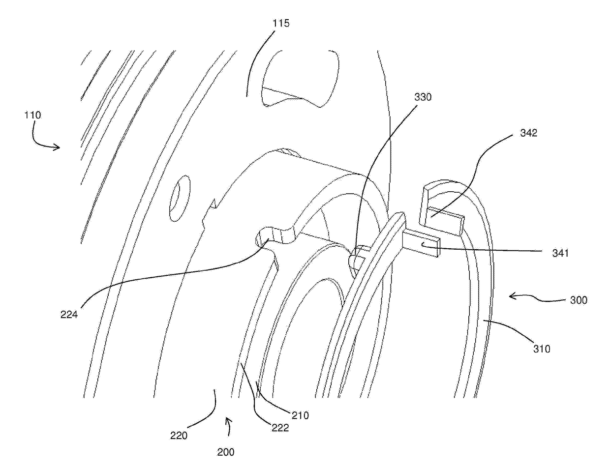
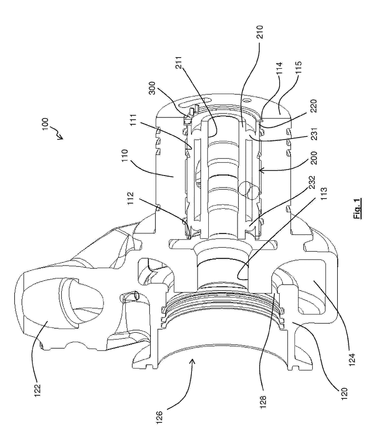
[0067]FIG. 1 illustrates a housing 100 for an expansion turbine. The expansion turbine may, for example, form part of an electrical generator. The housing 100 comprises a bearing housing 110 and a turbine housing 120. The bearing housing 110 and turbine housing 120 may be integrally formed or, alternatively, may be formed separately and fixed together using, for example, screws or bolts.

[0068]The turbine housing 120 comprises an inlet 122, a volute 124 and a generally cylindrical chamber 126. Chamber 126 is suitable for receipt of a turbine wheel (not shown) and, optionally, a stator. In use, a fluid enters the turbine housing via inlet 122, flows into the volute 124, and passes through an annular passage 128 into chamber 126. If present, the stator may be disposed upstream of the turbine wheel and may comprise a plurality of guide vanes. The guide vanes may be arranged to direct the fluid flowing through the annular chamber 126 onto blades of the turbine wheel. The fluid may pass t...


PUM


Abstract

A assembly comprises: a first member, a second member and an anti-rotation device. The first member is provided with a bore and a groove on a surface of the bore. At least a portion of the second member is disposed within the bore in the first member and a recess is provided on a generally axially facing surface of the portion of the second member. The anti-rotation device comprises an arcuate resilient body comprising a radially inner portion and a radially outer portion, the radially outer portion being received within the groove, the radially inner portion abutting a surface of the portion of the second member. A first anti-rotation feature is provided on the radially outer portion for cooperation with a complimentary feature of the first member. A second anti-rotation feature is provided on the radially inner portion, extending away from the radially inner portion of the body in a generally axial direction and is received within the recess on the second member.

Description

FIELD OF THE DISCLOSURE[0001]The present disclosure relates to an anti-rotation device that is arranged to cooperate with two adjacent elements so as to prevent relative rotation of the two elements.[0002]In particular, it may relate to a bearing unit comprising a bearing housing, a bearing assembly and an anti-rotation device that is arranged to prevent the bearing assembly from rotating relative to the bearing housing. The bearing unit may form part of a turbomachine such as a turbocharger or an expansion turbine of a waste heat recovery system.[0003]Alternatively, it may relate to a compressor housing comprising two members that cooperate to form a housing for a compressor wheel and an anti-rotation device that is arranged to prevent relative rotation of the two members. The compressor housing and compressor wheel may together form the compressor of a turbocharger. The two members of the compressor housing may comprise a bearing housing and a compressor cover respectively.[0004]I...

Claims


Application Information

Patent Timeline
Patent Type & Authority Applications(United States)
IPC IPC(8): F16B21/18
CPCF16B21/183F16B21/18
Inventor ROOKS, STEVEN C.
Owner CUMMINS LTD
Why Eureka
Try Eureka