
Seat pumping device for vehicle

a technology for vehicles and seats, applied in the direction of mechanically actuated clutches, transportation and packaging, moving seats, etc., can solve the problems of increasing weight and costs, and achieve the effects of reducing weight and costs, simplifying the structure of clutch devices and brake devices, and improving performan

Active Publication Date: 2017-09-07
HYUNDAI DYMOS
View PDF2 Cites 12 Cited by
  • Summary
  • Abstract
  • Description
  • Claims
  • Application Information

AI Technical Summary

Benefits of technology

The present invention is a seat pumping device for a vehicle that aims to be lightweight, cost-effective and reliable. It achieves this by simplifying the structures of the clutch device and the brake device, reducing their sizes and weights. Additionally, the device operates smoothly, improving its operational reliability. Overall, the invention provides an efficient and effective solution for vehicle seat pumping.

Problems solved by technology

In this case, it is necessary to further simplify a structure of the seat pumping device for a vehicle in the related art because the structure is complicated, which causes increases in weight and costs.

Method used


Image

  • Seat pumping device for vehicle
  • Seat pumping device for vehicle
  • Seat pumping device for vehicle

Examples


Embodiment Construction

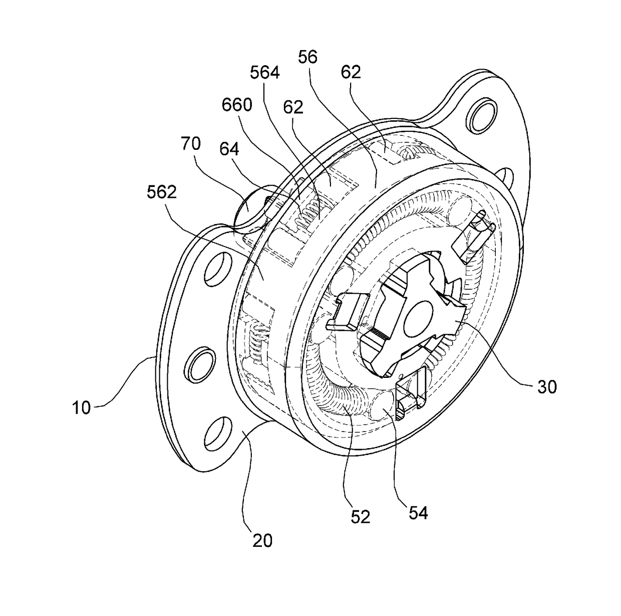
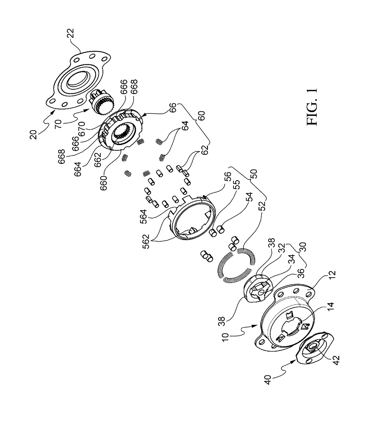
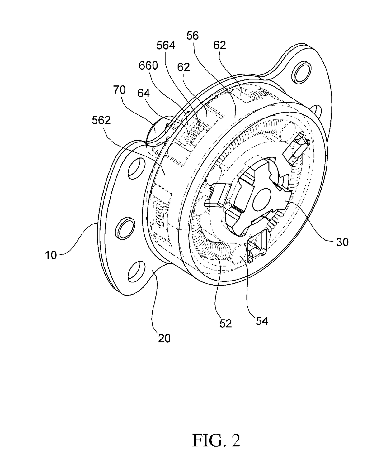
[0033]Hereinafter, an exemplary embodiment of the present invention will be described in detail with reference to the accompanying drawings. First, in denoting reference numerals to constituent elements of respective drawings, it should be noted that the same constituent elements will be designated by the same reference numerals, if possible, even though they are illustrated in different drawings. Further, in the following description of the present invention, a detailed description of publicly known configurations or functions incorporated herein will be omitted when it is determined that the detailed description may make the subject matter of the present invention unclear. Further, an exemplary embodiment of the present invention will be described below, but the technical spirit of the present invention is not limited thereto and may be modified and variously carried out by those skilled in the art.

[0034]FIG. 1 is an exploded perspective view of a seat pumping device for a vehicle...


PUM


Abstract

Disclosed is a seat pumping device for a vehicle. The present invention provides a seat pumping device for a vehicle, the seat pumping device including: a clutch device which is rotated clockwise or counterclockwise by receiving external manipulation force, and has one or more manipulation flanges that are disposed at a predetermined interval in a circumferential direction and protrude in an axial direction; and a brake device which has one or more manipulation grooves in which the manipulation flanges are accommodated to come into contact with the manipulation grooves clockwise or counterclockwise so that the brake device is rotated clockwise or counterclockwise by receiving the external manipulation force from the clutch device, and performs a brake function such that the brake device is not rotated clockwise and counterclockwise by external force that is not through the clutch device.

Description

CROSS-REFERENCE TO RELATED APPLICATIONS[0001]This application claims priority to and the benefit of Korean Patent Application No. 10-2016-0025844 filed in the Korean Intellectual Property Office on Mar. 3, 2016, the entire contents of which are incorporated herein by reference.TECHNICAL FIELD[0002]The present invention relates to a seat pumping device for a vehicle, and more particularly, to a seat pumping device for a vehicle which is light in weight, and has a small size and improved performance.BACKGROUND ART[0003]A seat pumping device for a vehicle in the related art refers to a device which is attached to a seat in order to allow an occupant seated in the seat to manually adjust a height of a seat cushion in accordance with his / her body type. When the occupant seated in the seat manipulates a lever handle, which is installed at a lateral side of the seat cushion, clockwise or counterclockwise, operating force of the lever handle is transmitted to a link mechanism through the se...

Claims


Application Information

Patent Timeline
Patent Type & Authority Applications(United States)
IPC IPC(8): B60N2/16
CPCB60N2/168B60N2/1635B60N2/1605B60N2/169B60N2/167F16D59/00F16D15/00F16D41/105
Inventor CHAE, SOO YOUNG
Owner HYUNDAI DYMOS
Learn More