Rotatable tube rack holder and tube rack rotator device for tube racks

a technology of rotatable tube racks and tube racks, which is applied in the direction of laboratory equipment, mixers, instruments, etc., can solve the problems of requiring a considerable amount of manual labor, affecting the quality of the product, so as to reduce time and effort and increase the number of samples

Inactive Publication Date: 2017-08-31
ROTAPURE LAB INSTR IVS
View PDF9 Cites 4 Cited by
  • Summary
  • Abstract
  • Description
  • Claims
  • Application Information

AI Technical Summary

Benefits of technology

[0016]According to the present invention, the rotatable tube rack holder for a laboratory sample inversion device includes one or more plates extending radially from the axis of rotation. One or more compartments located on these surfaces allow secure attachment of laboratory tube racks, each tube rack holding a plurality of test tubes with a sample. Rotation by a motor unit permits agitation of the samples, for instance biological material as a step in diagnostic or experimental procedures. Compartments are configured...

Problems solved by technology

Many such high-throughput procedures are not fully automated, but involve work-flow steps that require a considerable amount of manual labor.
These steps in the work-flow are often not only through-put limiting bottlenecks, but also arduous and time-consuming.
Furthermore, hands-on steps in high through-put procedures are likely to be comprised of a large number of serially iterated monotonous movements.
This represents very adverse ergonomics regimes and as such pose serious challenges to the work health environment.
Complete mixing by vortexing requires high speed swirling, which is an inefficient process.
Further, such vigorous vortexing may be detrimental to the integrity of the sample or added testing components, especially in the case of biological samples such as tissues, cells or larger organic molecules.
These instruments, however, are limi...

Method used


Image

  • Rotatable tube rack holder and tube rack rotator device for tube racks
  • Rotatable tube rack holder and tube rack rotator device for tube racks
  • Rotatable tube rack holder and tube rack rotator device for tube racks

Examples


example 1

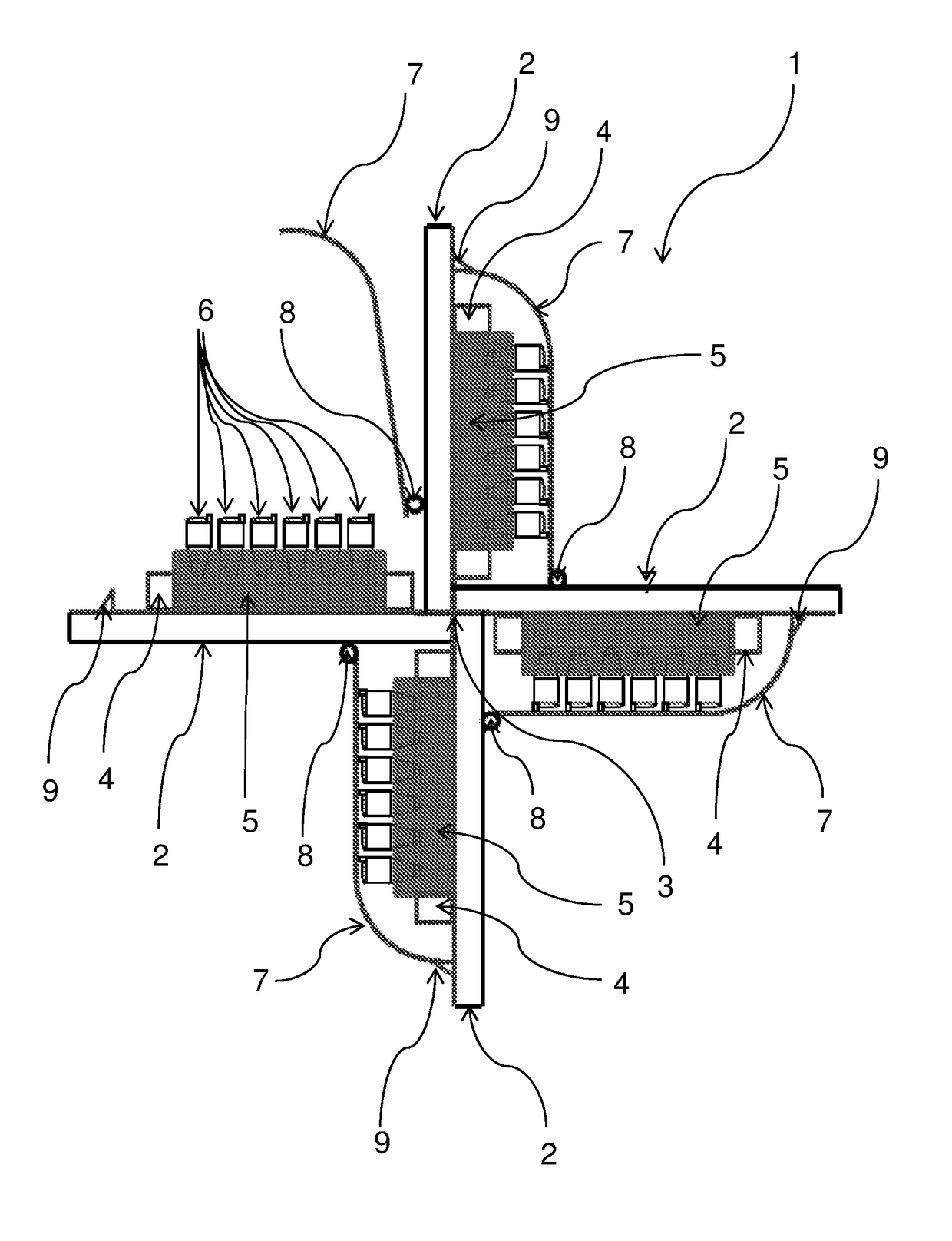
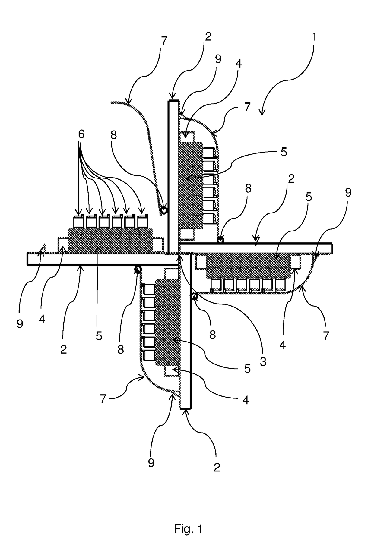
[0078]FIG. 1 shows an example of a rotatable tube rack holder for a tube rack rotator device according to the present invention from a side view. The rotatable tube rack holder for a tube rack rotator device 1 comprises: four plates 2 extending radially from an axis of rotation 3; four compartments 4 for tightly holding one or more tube rack(s) 5, each tube rack configured to hold a plurality of tubes 6, wherein said compartments 4 are attached to one side of said plates 2 and configured such that said one or more tube rack(s) 5 can be placed inside said compartments 4 from a direction substantially perpendicular to said plate 2; and a locking mechanism 7 for each of said compartments 4 and configured such that when said tube rack(s) 5 holding a plurality of said tubes 6 is / are placed inside said compartment 4, said tubes 6 are restricted from moving in a direction perpendicular to said plate 2. In this example, the plates 2 comprise four plates forming four radially extending plate...

example 2

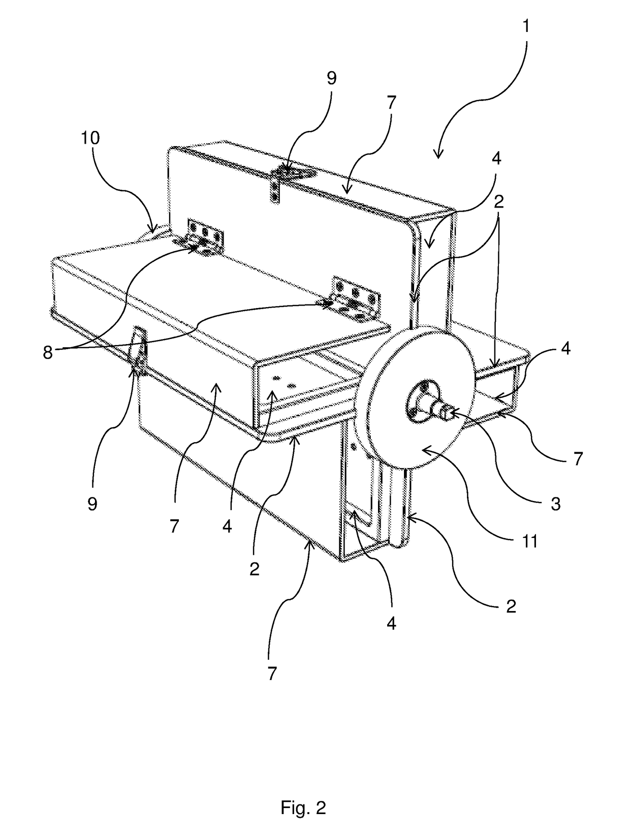
[0079]FIG. 2 shows another example of a rotatable tube rack holder for a tube rack rotator device according to the present invention from a first perspective. The rotatable tube rack holder for a tube rack rotator device 1 comprises: three plates 2 extending radially from an axis of rotation 3; four compartments 4 for tightly holding one or more tube rack(s), each tube rack configured to hold a plurality of tubes, wherein said compartments 4 are attached to one side of said plates 2 and configured such that said one or more tube rack(s) can be placed inside said compartments 4 from a direction substantially perpendicular to said plate 2; and a locking mechanism 7 for each of said compartments 4 and configured such that when said tube rack(s) holding a plurality of said tubes is / are placed inside said compartment 4, said tubes are restricted from moving in a direction perpendicular to said plate 2. In this example, the plates comprise three plates and the three plates form four radia...

example 3

[0080]FIG. 3 shows another example of a rotatable tube rack holder for a tube rack rotator device according to the present invention from a second perspective. The rotatable tube rack holder for a tube rack rotator device 1 comprises: three plates 2 extending radially from an axis of rotation 3; four compartments 4 for tightly holding one or more tube rack(s), each tube rack configured to hold a plurality of tubes, wherein said compartments 4 are attached to one side of said plates 2 and configured such that said one or more tube rack(s) can be placed inside said compartments 4 from a direction substantially perpendicular to said plate 2; and a locking mechanism 7 for each of said compartments 4 and configured such that when said tube rack(s) holding a plurality of said tubes is / are placed inside said compartment 4, said tubes are restricted from moving in a direction perpendicular to said plate 2. In this example, the plates comprise three plates and the three plates form four radi...


PUM


Abstract

The present disclosure relates to a rotatable tube rack holder for a tube rack rotator device, comprising: one or more plate(s) extending radially from an axis of rotation; one or more compartment(s) for tightly holding one or more tube rack(s) configured to hold a plurality of tubes, said compartment(s) is/are attached to at least one side of said plate(s); and one locking mechanism for each of said compartment and configured such that when said tube rack(s) holding a plurality of said tubes is/are placed inside said compartment, said tubes are restricted from moving in a direction perpendicular to said plate.

Description

FIELD OF INVENTION[0001]The present invention relates to a rotatable tube rack holder and tube rack rotator device for tube racks.BACKGROUND OF INVENTION[0002]Modern research or diagnostic laboratories are increasingly moving towards high through-put procedures. This is true for laboratories with a chemical or biological focus in industry (applied research) as well as academia (basic research) and the health care sector (clinical diagnostics). Many such high-throughput procedures are not fully automated, but involve work-flow steps that require a considerable amount of manual labor. These steps in the work-flow are often not only through-put limiting bottlenecks, but also arduous and time-consuming. Furthermore, hands-on steps in high through-put procedures are likely to be comprised of a large number of serially iterated monotonous movements. This represents very adverse ergonomics regimes and as such pose serious challenges to the work health environment. In order to take advantag...

Claims


Application Information

Patent Timeline
IPC IPC(8): B01F9/00B01L9/06B01F29/83
CPCB01F9/0021B01L9/06B01F9/0025B01F9/002G01N35/04B01F9/12B01F9/0029G01N2035/0441B01F9/0014B01L2300/043B01L2300/0609B01L2300/0809G01N2035/00524G01N2035/0439B01F29/321B01F29/322B01F29/34B01F29/331B01F29/30B01F29/83B01F29/333
Inventor JAKOBSEN, JANUS SCHOUNIELSEN, STEEN
Owner ROTAPURE LAB INSTR IVS
Why Eureka
Try Eureka