
Method of coupling a motion sensor to a piece of equipment

a motion sensor and equipment technology, applied in the field of mounts, can solve problems such as the inability to instrument a piece of equipmen

Active Publication Date: 2017-08-17
NEWLIGHT CAPITAL LLC
View PDF10 Cites 29 Cited by
  • Summary
  • Abstract
  • Description
  • Claims
  • Application Information

AI Technical Summary

Benefits of technology

The invention is a method of attaching a motion sensor to sports equipment without causing any damage or modification to the equipment. The attachment is made through a durable and secure mount that allows for easy installation and removal. The motion sensor can provide information on the position and orientation of the sensor relative to the equipment, which can be useful in analyzing the movement of the equipment. The attachment can be retrofitted to existing equipment, and the mount can be easily replaced without modifying the equipment. The attachment can also include a visual marker for visually obtaining motion. The invention can be used in a variety of sports equipment and make it easier to gather data on movements during training or games.

Problems solved by technology

In addition, certain sports may not allow the piece of equipment to be instrumented during match play.

Method used


Image

  • Method of coupling a motion sensor to a piece of equipment
  • Method of coupling a motion sensor to a piece of equipment
  • Method of coupling a motion sensor to a piece of equipment

Examples


Embodiment Construction

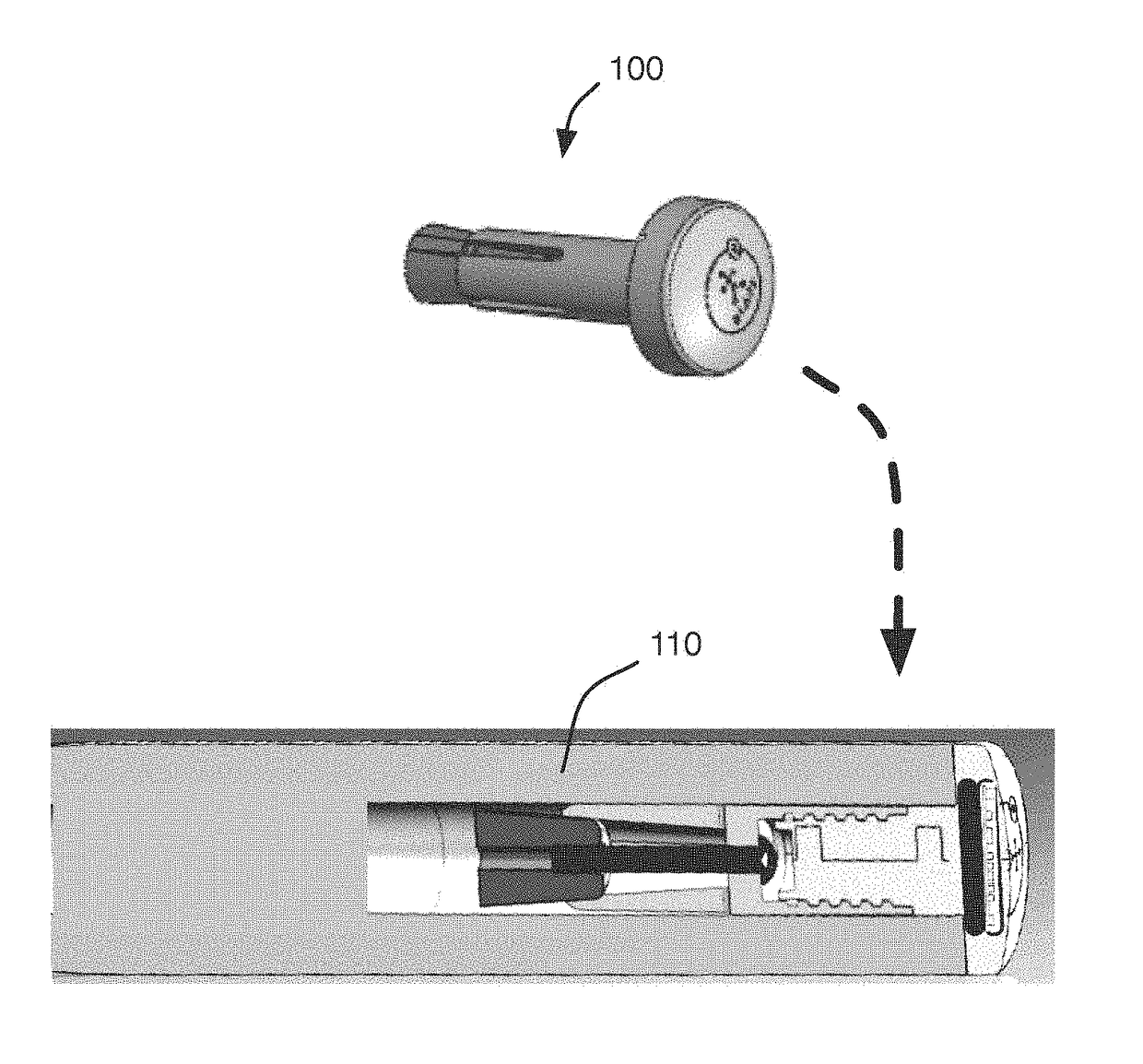
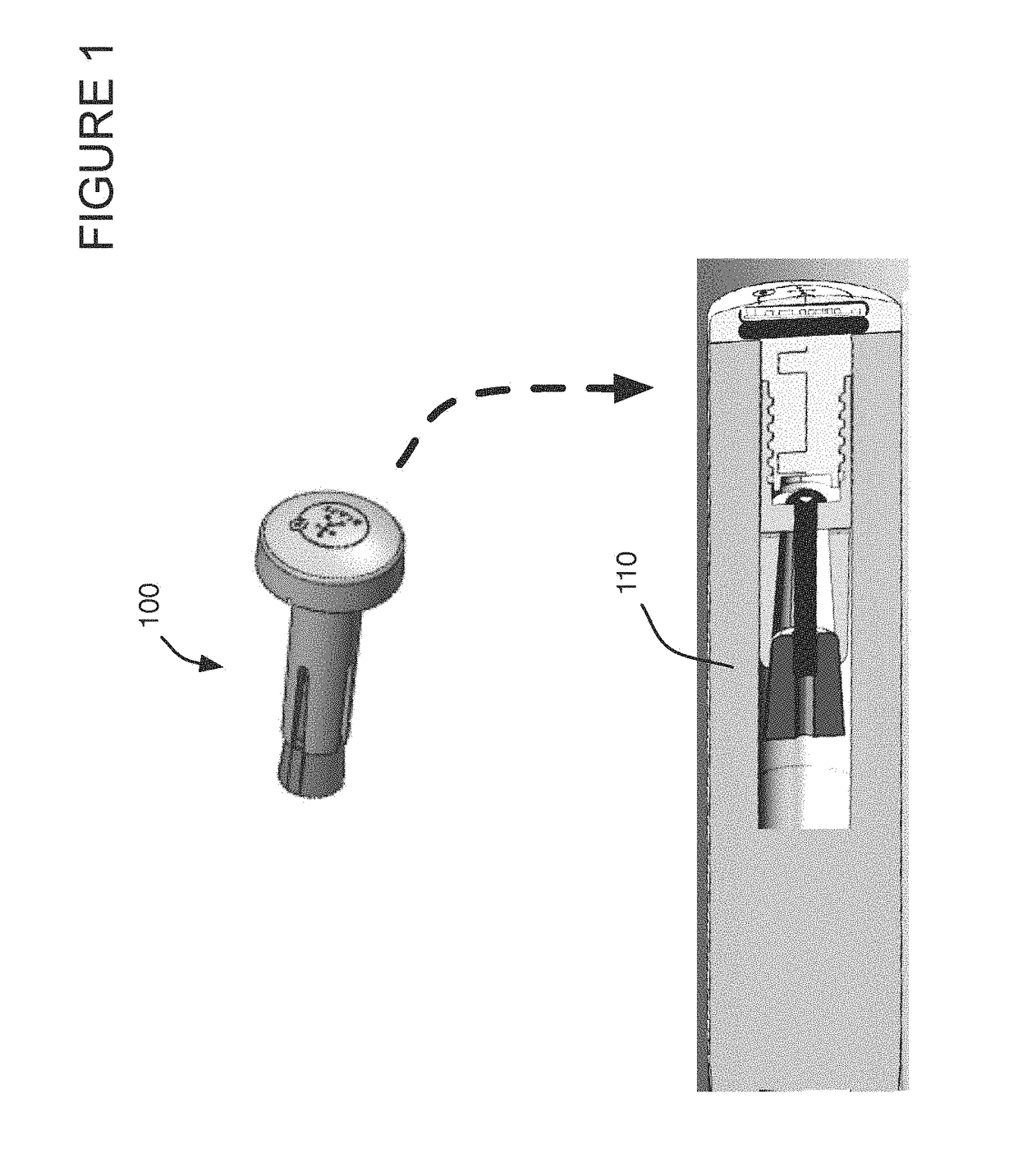
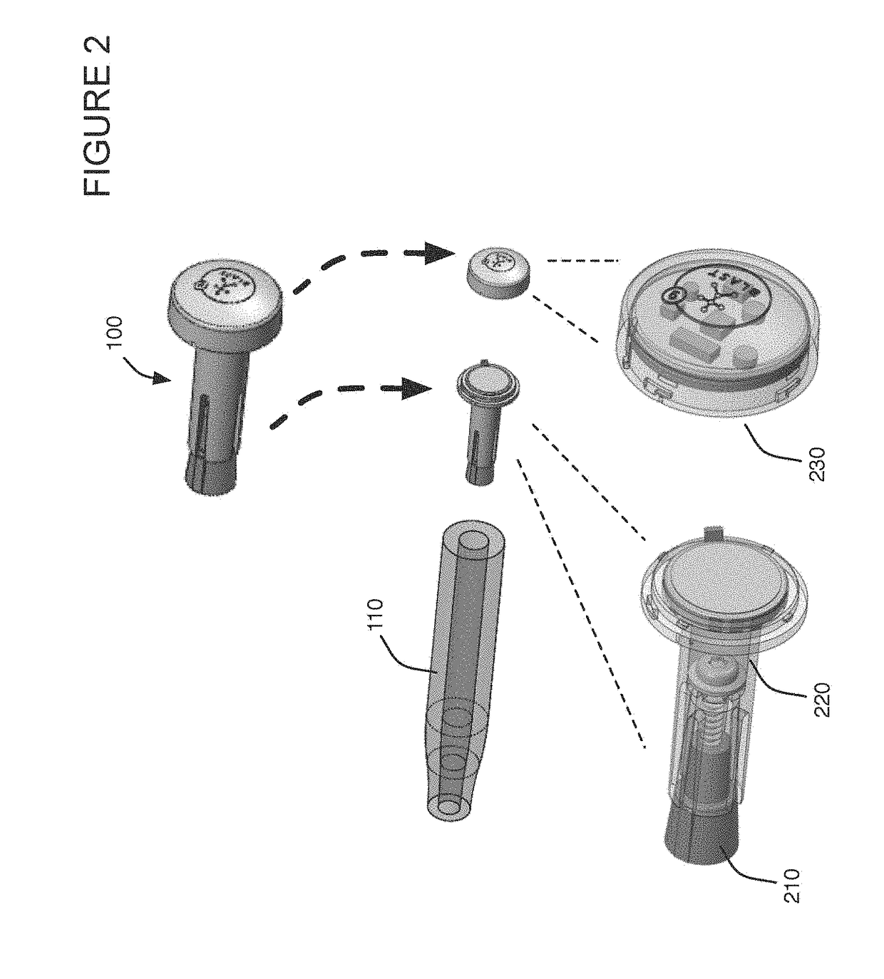
[0092]A method of coupling a motion sensor to a piece of equipment will now be described. In the following exemplary description numerous specific details are set forth in order to provide a more thorough understanding of the ideas described throughout this specification. It will be apparent, however, to an artisan of ordinary skill that embodiments of ideas described herein may be practiced without incorporating all aspects of the specific details described herein. In other instances, specific aspects well known to those of ordinary skill in the art have not been described in detail so as not to obscure the disclosure. Readers should note that although examples of the innovative concepts are set forth throughout this disclosure, the claims, and the full scope of any equivalents, are what define the invention. One skilled in the art will recognize that embodiments of the invention may be utilized in any equipment capable of coupling with the apparatus. This includes any piece of spo...


PUM


Abstract

Method for coupling a sensor to a piece of equipment, such as a golf club, baseball bat, or tennis racket, that ensures that the sensor is in a known position and orientation relative to the equipment. Compensates and calibrates for degrees of freedom introduced in manufacturing and installation. The method may include manufacturing a sensor receiver that aligns with equipment in a fixed orientation, and that holds a sensor housing in a fixed orientation relative to the receiver. Remaining uncertainties in sensor position and orientation may be addressed using post-installation calibration. Calibration may include performing specific calibration movements with the equipment and analyzing the sensor data collected during these calibration movements.

Description

[0001]This application is a continuation-in-part of U.S. Utility patent application Ser. No. 15 / 011,100 filed 29 Jan. 2016, which is a continuation-in-part of U.S. Utility patent application Ser. No. 13 / 688,213 filed 29 Nov. 2012, which is a continuation-in-part of U.S. Utility patent application Ser. No. 13 / 306,869 filed 29 Nov. 2011, which is a continuation-in-part of U.S. Utility patent application Ser. No. 13 / 191,309 filed 26 Jul. 2011, which is a continuation-in-part of U.S. Utility patent application Ser. No. 13 / 048,850 filed 15 Mar. 2011, which is a continuation-in-part of U.S. Utility patent application Ser. No. 12 / 901,806 filed 11 Oct. 2010, which is a continuation-in-part of U.S. Utility patent application Ser. No. 12 / 868,882 filed 26 Aug. 2010, the specifications of which are hereby incorporated herein by reference.BACKGROUND OF THE INVENTION[0002]Field of the Invention[0003]One or more embodiments setting forth the ideas described throughout this disclosure pertain to th...

Claims


Application Information

Patent Timeline
Patent Type & Authority Applications(United States)
IPC IPC(8): G01D11/24A63B69/00A63B69/38A63B24/00A63B69/36
CPCG01D11/245A63B24/0003A63B69/3632A63B69/38A63B2220/833A63B2220/40A63B2220/34A63B2069/0008A63B69/0002A61B5/6895A63B69/0093A63C11/00A63B21/0724A63B21/0726A63B49/00A63B53/00A63B53/14G01C19/00G01S19/19G01S19/35G01S19/36G06F3/011A61B2562/0219A63B2071/0063A63B2209/02A63B2220/12A63B2220/16A63B2220/17A63B2220/30A63B2220/44A63B2220/806A63B2225/15A63B2225/20A63B2225/50A63B2225/54A63C2203/18A63C2203/22A63C2203/24G06F3/0346A63B21/4035A63B60/16A63B60/42A63B59/50A61B5/1122A61B2560/0223A61B2560/0443A61B2560/0456A42B3/0433A63B2071/0694A63B2225/60A63C5/03A63C11/228A63C17/00G01C21/166
Inventor MARTIN, JOSHUABOSE, BHASKARBENTLEY, MICHAELKAPS, RYAN
Owner NEWLIGHT CAPITAL LLC
Learn More