Printing apparatus and medium support method
- Summary
- Abstract
- Description
- Claims
- Application Information
AI Technical Summary
Benefits of technology
Problems solved by technology
Method used
Image


Examples
first embodiment (
FIGS. 1 to 8B)
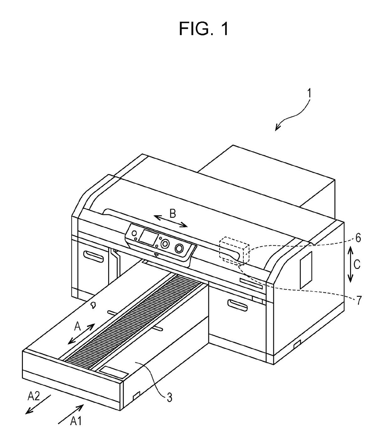
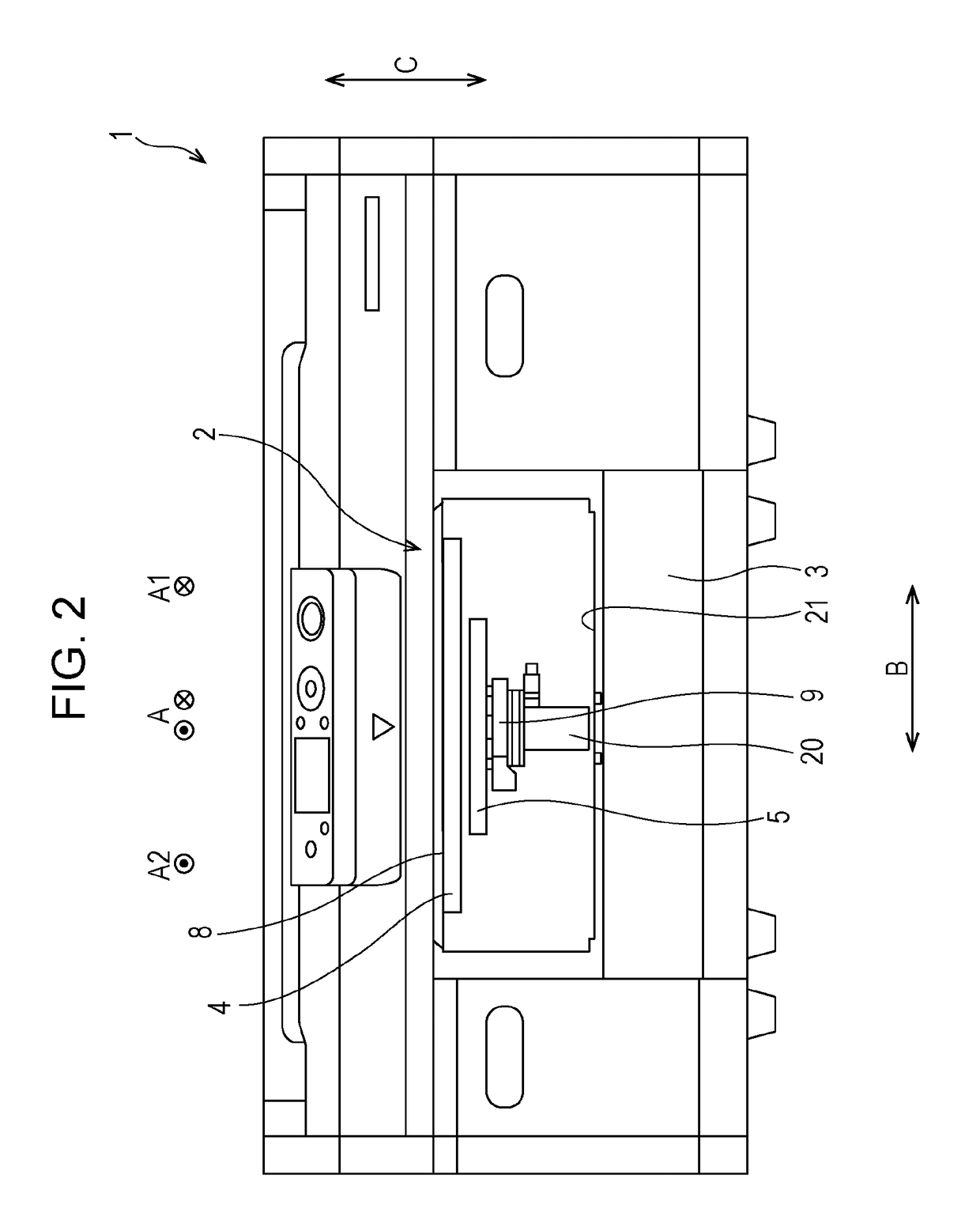
[0030]FIG. 1 is a schematic perspective view of the printing apparatus 1 according to a first embodiment, and illustrates a state where a medium support unit 2 is set at a print starting position. FIG. 2 is a schematic front view of the printing apparatus 1 of the embodiment. FIG. 3 is a schematic plan view of the printing apparatus 1 of the embodiment, and FIG. 4 is a schematic side view of the printing apparatus 1 of the embodiment. Each of FIGS. 3 and 4 illustrates a state where the medium support unit 2 is set at a position for setting a medium M (see FIG. 5).
[0031]The printing apparatus 1 of the embodiment includes the medium support unit 2 that moves in a movement direction A while supporting the medium M on a support surface 8 of a tray 4. The medium support unit 2 includes the tray 4 serving as a support unit of the medium M. The printing apparatus 1 includes a medium transport unit 3 configured to transport the medium M supported by the tray 4 in the movement ...
second embodiment (fig.9)
Second Embodiment (FIG. 9)
[0050]Next, a printing apparatus 1 according to a second embodiment will be described in detail with reference to the accompanying drawings.
[0051]FIG. 9 illustrates a schematic plan view of a stage 5 as a principal portion of the printing apparatus 1 of the second embodiment, and corresponds to FIG. 7 of the printing apparatus 1 of the first embodiment.
[0052]The printing apparatus 1 of the second embodiment has the same constitution as the printing apparatus 1 of the first embodiment except for the constitution of the stage 5.
[0053]The printing apparatus 1 of the first embodiment is constituted such that the tray 4 is detached from the stage 5, the orientation thereof is changed, and the tray 4 is attached again to the stage 5 when the setting direction of the tray 4 with respect to the stage 5 is changed.
[0054]In contrast, the printing apparatus 1 of the second embodiment is constituted such that the tray 4 is rotationally moved (revolved) relative to the ...
third embodiment (fig.10)
Third Embodiment (FIG. 10)
[0060]FIG. 10 illustrates a schematic plan view of a stage 5 as a principal portion of the printing apparatus 1 of the third embodiment, and corresponds to FIG. 7 of the printing apparatus 1 of the first embodiment and FIG. 9 of the printing apparatus 1 of the second embodiment.
[0061]Note that the printing apparatus 1 of the third embodiment has the same constitution as the printing apparatus 1 of the second embodiment except for the constitution of the fixing portion 22.
[0062]The fixing portions 22 of the printing apparatus 1 of the second embodiment are constituted of the projections 22a and 22b that are pushed in and pushed out with respect to the insertion opening 13.
[0063]Meanwhile, the fixing portions 22 of the third embodiment are constituted of retreat paths 22c, 22d, 22e, and 22f that are provided in insertion openings 13.
[0064]To be specific, as shown in FIG. 10, the retreat path 22c extending in a direction E1 along the movement direction A is fo...
PUM
 Abstract
Description
Claims
Application Information
 - R&D
- Intellectual Property
- Life Sciences
- Materials
- Tech Scout
- Unparalleled Data Quality
- Higher Quality Content
- 60% Fewer Hallucinations
Browse by: Latest US Patents, China's latest patents, Technical Efficacy Thesaurus, Application Domain, Technology Topic, Popular Technical Reports.
© 2025 PatSnap. All rights reserved.Legal|Privacy policy|Modern Slavery Act Transparency Statement|Sitemap|About US| Contact US: help@patsnap.com