
Power wireless transmitter in magnetic resonance-based wireless power transmission system

a wireless transmitter and wireless transmission technology, applied in the direction of electrical equipment, circuit arrangements, etc., can solve the problems of deteriorating wireless power transmission efficiency, and affecting the efficiency of wireless transmission

Inactive Publication Date: 2017-08-10
PR TECH INC
View PDF7 Cites 6 Cited by
  • Summary
  • Abstract
  • Description
  • Claims
  • Application Information

AI Technical Summary

Benefits of technology

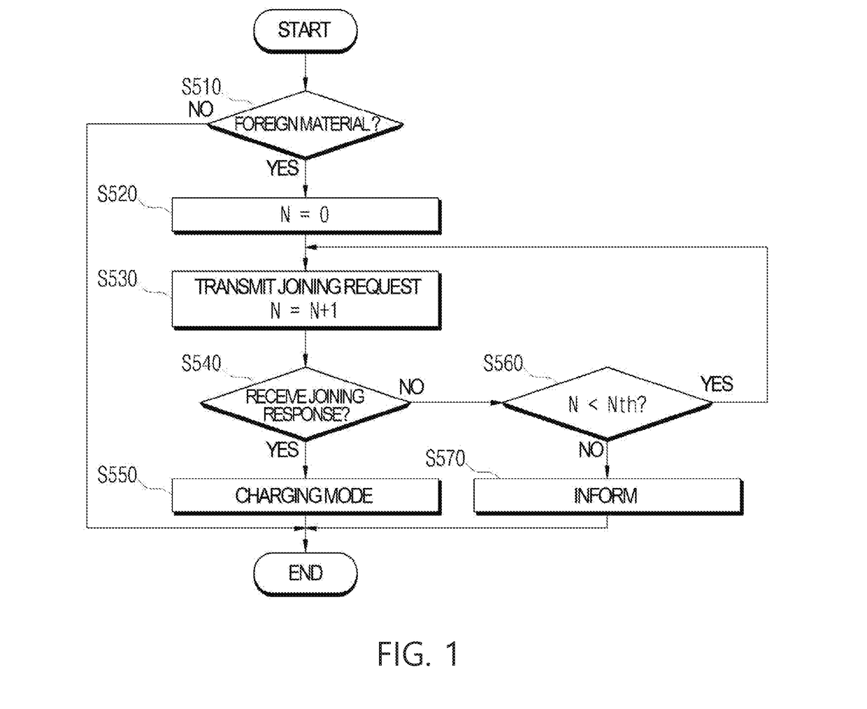
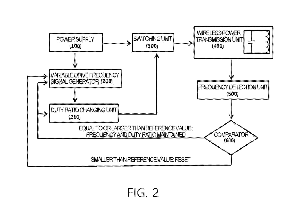
This patent is about a power wireless transmitter used in a magnetic resonance-based wireless power transmission system. The patent involves determining the resonance frequency, drive frequency, and duty ratio of the wireless power transmitter based on the presence of metals. This results in an efficient wireless power transmission at a maximum output. In summary, this patent aims to improve the effectiveness of wireless power transmission in magnetic resonance systems.

Problems solved by technology

However, a resonance frequency of a transmitter does not coincide with that of a receiver, an efficient wireless power transmission may not be achieved.
However, this approach may have a limitation in terms of times of the changes of the capacitance of the wireless power transmitter.
Otherwise, the wireless power transmission efficiency may be deteriorated.

Method used


Image

  • Power wireless transmitter in magnetic resonance-based wireless power transmission system
  • Power wireless transmitter in magnetic resonance-based wireless power transmission system
  • Power wireless transmitter in magnetic resonance-based wireless power transmission system

Examples


Embodiment Construction

[0025]Examples of various embodiments are illustrated and described further below. It will be understood that the description herein is not intended to limit the claims to the specific embodiments described. On the contrary, it is intended to cover alternatives, modifications, and equivalents as may be included within the spirit and scope of the present disclosure as defined by the appended claims. Example embodiments will be described in more detail with reference to the accompanying drawings. The present disclosure, however, may be embodied in various different forms, and should not be construed as being limited to only the illustrated embodiments herein. Rather, these embodiments are provided as examples so that this disclosure will be thorough and complete, and will fully convey the aspects and features of the present disclosure to those skilled in the art.

[0026]It will be understood that, although the terms “first”, “second”, “third”, and so on may be used herein to describe va...


PUM


Abstract

The present disclosure is to provide a power wireless transmitter in a magnetic resonance-based wireless power transmission system, wherein when, due to a presence of a metal, an output from the wireless power transmitter has a change in a resonance frequency thereof, a drive frequency and / or duty ratio with a maximum output therefrom are determined to be applied for a transmission from the wireless power transmitter, thereby to achieve an efficient wireless power transmission.

Description

CROSS-REFERENCE TO RELATED APPLICATION[0001]This application claims the benefit of Korea patent application No. 10-2015-0108741, filed on Jul. 31, 2015, the entire content of which is incorporated herein by reference for all purposes as if fully set forth herein.BACKGROUND[0002]Field of the Present Disclosure[0003]The present disclosure relates to a power wireless transmitter in a magnetic resonance-based wireless power transmission system, and, in particularly, to a power wireless transmitter in a magnetic resonance-based wireless power transmission system, wherein when, due to a presence of a metal, an output from the wireless power transmitter has a change in a resonance frequency thereof, a drive frequency and / or duty ratio with a maximum output therefrom are determined to be applied for a transmission from the wireless power transmitter, thereby to achieve an efficient wireless power transmission.[0004]Discussion of Related Art[0005]Generally, a magnetic resonance-based wireles...

Claims


Application Information

Patent Timeline
IPC IPC(8): H02J50/12H02J50/60
CPCH02J50/60H02J50/12H02J50/90
Inventor OH, YEONMICHOI, CHANGUK
Owner PR TECH INC
Learn More