Projectile having increased velocity and aerodynamic performance

a technology of aerodynamic performance and projectiles, applied in the field of projectiles with increased velocity and aerodynamic performance, can solve the problems of tearing relatively fragile moving parts apart, complex manufacturing of such expanding cones, and high probability of failure during deploymen

Active Publication Date: 2017-08-10
ADAMS RICHARD D
View PDF5 Cites 9 Cited by
  • Summary
  • Abstract
  • Description
  • Claims
  • Application Information

AI Technical Summary

Benefits of technology

[0008]A projectile fired from a barrel by highly pressurized gas developed independent of the projectile is disclosed. The projectile is configured having at least one chamber at its aft portion, the chamber having rear walls generally coincident with a circumference of the projectile body. A member in the chamber has a circular region at the open end of the chamber, forming an annular opening that allows the highly pressurized gas into the chamber and exert force against a forward wall of the chamber, assisting in propelling the projectile forward.

Problems solved by technology

One problem with this type of design is not only the complexity of manufacturing such an expanding cone, but the higher probability of failure during its deployment due to a tremendous increase in the number of moving parts.
In addition, the extreme rate of revolution of a bullet, which is typically well in excess of 100,000 RPM, may tear relatively fragile moving parts apart due to centrifugal force.
Shrapnel that may be flung from a projectile rotating that fast would be devastating.
Another problem with this type of design is the change in center of gravity and center of pressure of the projectile while the projectile's cone is in the process of changing shapes (extending and ejecting parts, such as with the ejection of the pressure plate in Hall's design).
Once the cone in these previously mentioned designs are extended (fully deployed position), there could actually be a loss of overall area for the explosion to push off against, especially since the lack of outer side walls of the concentric cones would not capture much of the explosive force, and may even allow some of the explosive force to move in between the expanding rings (cones), deforming the cone altogether.
Some other designs, such as Sieling's U.S. Pat. No. 3,809,339 attempt to overcome the moveable / extendable boat tail or cone by the use of what the inventor calls “stings,” these stings, while eliminating some of the drag caused by disrupted airflow at the aft of the projectile, do not assist the projectile's performance by increasing the explosion “push-off” area, as well as having no chamber walls to contain the explosive force.

Method used


Image

  • Projectile having increased velocity and aerodynamic performance
  • Projectile having increased velocity and aerodynamic performance
  • Projectile having increased velocity and aerodynamic performance

Examples


Embodiment Construction

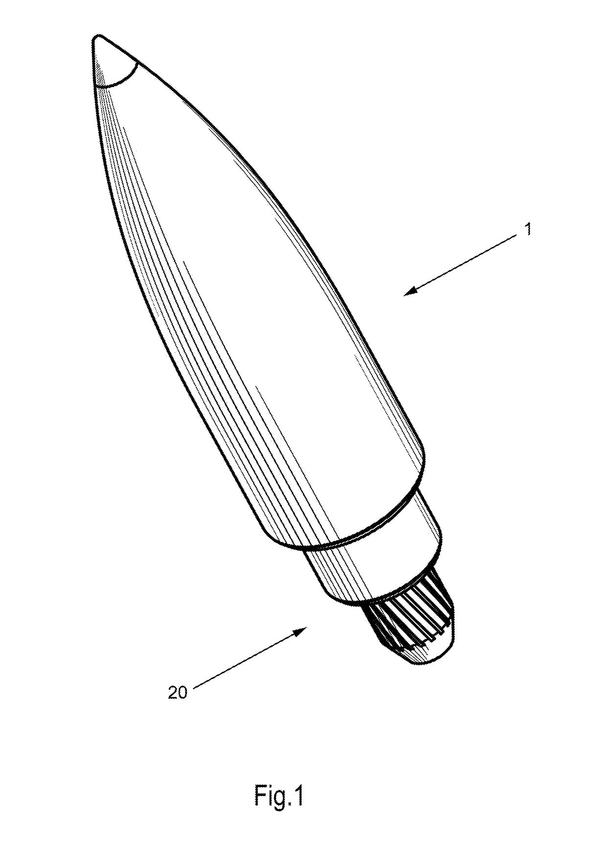
[0021]Referring to the drawings, FIG. 1 pictorially depicts a front perspective view of a projectile 1 with a portion 20 of the instant invention attached to its aft section. Portion 20, as will be explained, has a larger surface area for propulsion gasses to push against than a projectile of the prior art of the same diameter, enabling projectile 1 to be propelled with a greater velocity for the same amount of propellant as a prior art projectile having the same weight. In addition, portion 20 extends from a rear of projectile 1 into a region where a partial vacuum forms during projectile flight, filling such region and promoting smoother airflow around a rear of the projectile.

[0022]FIG. 2 depicts an aft perspective view of the projectile assembly 1, as well as the components of portion 20, which is attached to or constructed integral with a rear of projectile body assembly 30. A trailing edge of the projectile body assembly 30 includes an extended outer jacket wall 32, which form...


PUM


Abstract

A streamlined projectile is disclosed that includes a base or rear having a plurality of concentric sections located within each other at the aft of the projectile and in successively smaller sizes. Within each concentric section is a chamber having a wall perpendicular to expanding combustion gasses, with the total area of these walls being greater than an area of the rear of the projectile itself. This creates a larger projectile base for a propellant to push against and for that explosion to be held within the section chamber for a longer period than that of a standard boattail or flat-tail projectile. In addition, the concentric sections at least partially negate atmospheric drag by occupying the region behind the projectile where a partial vacuum forms, resulting in a projectile that will go faster and further for a given propellant charge.

Description

CROSS REFERENCE TO RELATED APPLICATIONS[0001]This application claims the benefit of Applicant's provisional application No. 62 / 291,319, filed Feb. 4, 2016, which is hereby incorporated in its entirety by reference.FIELD OF THE INVENTION[0002]This invention relates generally to firearm and gun ammunition, and particularly to such ammunition having an increased base area for propellant to push against, resulting in increased muzzle velocity for a given amount of charge, and also producing reduced drag so that such ammunition is propelled faster and further than conventional ammunition.BACKGROUND OF THE INVENTION[0003]Most conventional projectiles such as bullets or artillery shells are aerodynamically shaped to increase their speed and overall performance. Most commonly, the rear of a projectile fired from a firearm, artillery or the like is either cylindrical, as is the case with most artillery shells and larger caliber bullets, or configured as a “boattail”. The boattail is a trunca...

Claims


Application Information

Patent Timeline
Patent Type & Authority Applications(United States)
IPC IPC(8): F42B10/40F42B12/74
CPCF42B12/74F42B10/40F42B10/38F42B10/44
Inventor ADAMS, RICHARD D.
Owner ADAMS RICHARD D
Why Eureka
Try Eureka