Depth imaging correction apparatus, imaging apparatus, and depth image correction method
a correction apparatus and depth imaging technology, applied in the field of depth image correction apparatus, can solve the problems of inaccurate evaluation of correlation, one type of incorrect evaluation, and generation of one type of incorrect evaluation, and achieve the effect of accurate correction
- Summary
- Abstract
- Description
- Claims
- Application Information
AI Technical Summary
Benefits of technology
Problems solved by technology
Method used
Image

Examples
embodiment 1
[0028]Embodiment 1 of the present invention will be described with reference to the drawings. In the following description, a digital camera is used as an example of an imaging apparatus which includes a depth image generation apparatus (depth image processing apparatus) of the present invention, but application of the present invention is not limited to this.
[0029]In a description with reference to a drawing, a same reference sign denoted by a composing element indicates a same composing element even if the drawing number is different, and redundant description is minimized.
[0030]
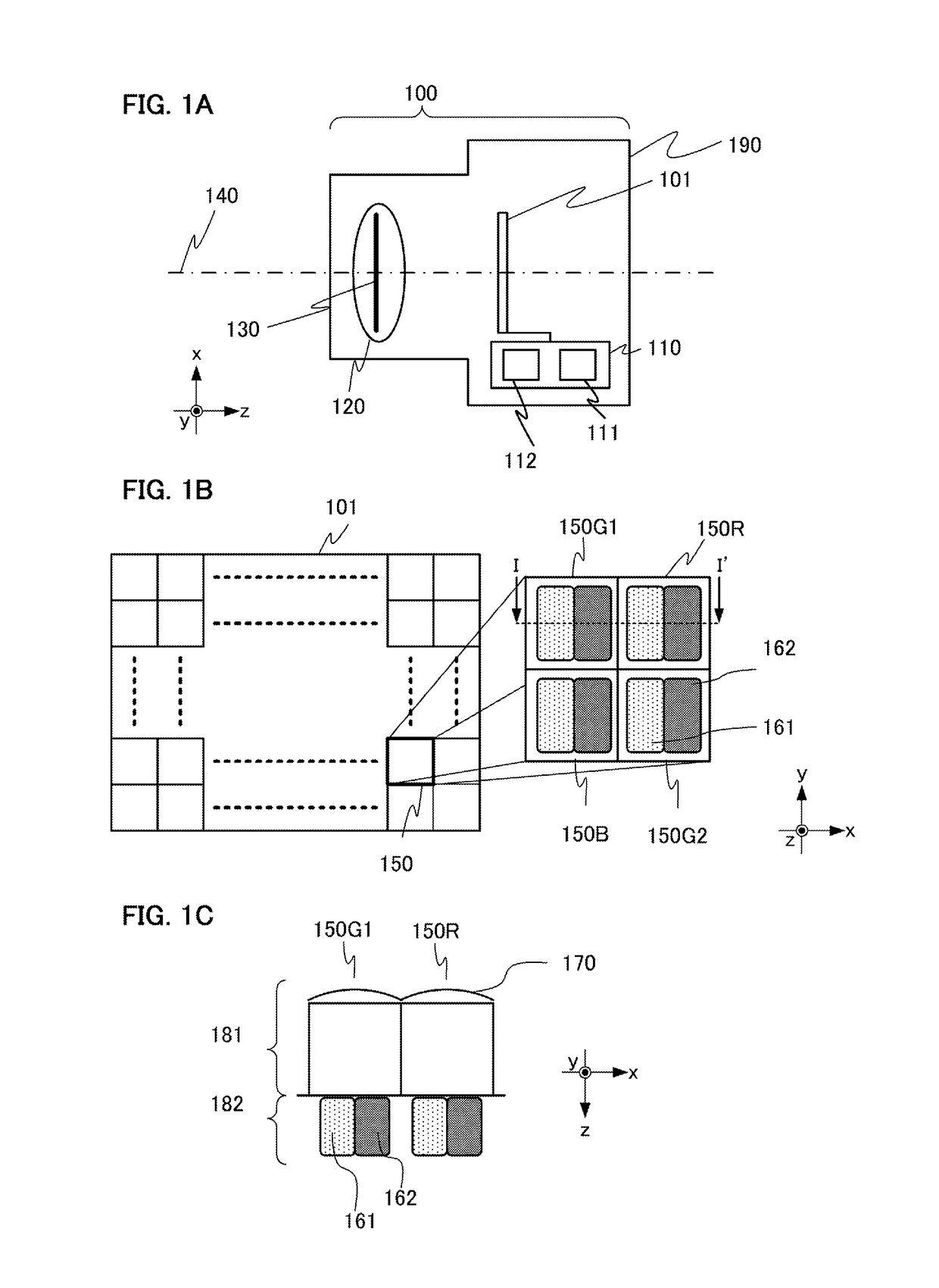
[0031]FIG. 1A is a digital camera 100 which includes a depth image generation apparatus 110 according to this embodiment. The digital camera 100 is constituted by an image forming optical system 120, an image pickup element 101, a depth image generation apparatus 110, an image generation unit (not illustrated), a lens driving control unit (not illustrated), and an image signal storage unit (not illustrated...
embodiment 2
[0086]A depth image generation apparatus 110 according to Embodiment 2 of the present invention will be described. FIG. 7A is a flow chart depicting an operation of the depth image generation processing which is performed by the depth image generation apparatus 110 according to this embodiment. FIG. 7B is a data flow chart in the depth image generation processing.
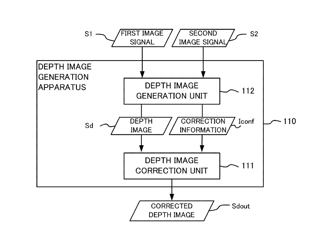
[0087]In this embodiment, the depth image generation apparatus 110 includes the depth image generation unit 112 and the depth image correction unit 111, just like Embodiment 1. The depth image generation unit 112 according to this embodiment generates the correction information Iconf including the depth image Sd, the first confidence Iconf1 and the second confidence Iconf2, in the same manner as Embodiment 1. The depth image correction unit 111 according to this embodiment performs the first depth correction processing based on the first confidence Iconf1 and the second depth correction processing based on the second confid...
embodiment 3
[0091]A depth image generation apparatus according to Embodiment 3 of the present invention will be described. In this embodiment, instead of correcting the depth values considering the depth difference in the first depth correction processing, the depth image is divided into a plurality of layers in accordance with the depth values, and correction is performed using the depth values on a same layer.
[0092]FIG. 8A is a flow chart depicting the operation of the depth image generation apparatus 110. A difference from Embodiment 1 is that the layer division processing S870 is added. Further, the processing content to be executed is different between the first depth correction processing S350 in Embodiment 1 and the first depth correction processing S850 of this embodiment. The depth image generation processing S330, the correction information generation processing S340, and the second depth correction processing S360 are the same as Embodiment 1. In the following, description on aspects...
PUM
 Abstract
Description
Claims
Application Information
 - R&D
- Intellectual Property
- Life Sciences
- Materials
- Tech Scout
- Unparalleled Data Quality
- Higher Quality Content
- 60% Fewer Hallucinations
Browse by: Latest US Patents, China's latest patents, Technical Efficacy Thesaurus, Application Domain, Technology Topic, Popular Technical Reports.
© 2025 PatSnap. All rights reserved.Legal|Privacy policy|Modern Slavery Act Transparency Statement|Sitemap|About US| Contact US: help@patsnap.com