
Multifunction Valve

a multi-functional, valve technology, applied in the direction of valve arrangements, plug valves, mechanical equipment, etc., can solve the problems of large volume within the fluid circuit, lack of fine precision control, etc., and achieve the effect of compact size, precise flow rate control, and simple design and assembly

Active Publication Date: 2017-08-03
MAXITROL
View PDF7 Cites 1 Cited by
  • Summary
  • Abstract
  • Description
  • Claims
  • Application Information

AI Technical Summary

Benefits of technology

The present invention provides a multi-function valve that has the advantages of being simple and easy to assemble, compact in size, and precise in flow rate control. The valve has a body that has an inlet and an outlet, and a flow control gate that is placed between these two points. The valve body may also have an upper and lower inlet branches, and an interior chamber that contains the flow control gate. The valve also has a control shaft that is positioned within the interior chamber of the valve body. The valve has a radiused feature at both the inlet and outlet, which increases the surface area where it comes into contact with other fluid circuit components.

Problems solved by technology

Conventional control systems may include valves having complex mechanisms including many components and complicated assembly.
These valves may suffer from a lack of fine precision control, and require a larger volume within the fluid circuit.

Method used


Image

  • Multifunction Valve
  • Multifunction Valve
  • Multifunction Valve

Examples


Embodiment Construction

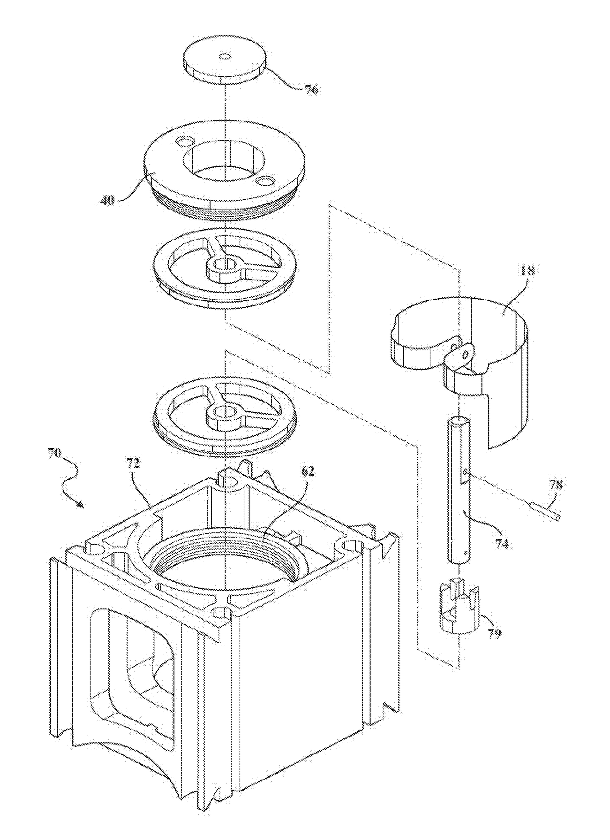
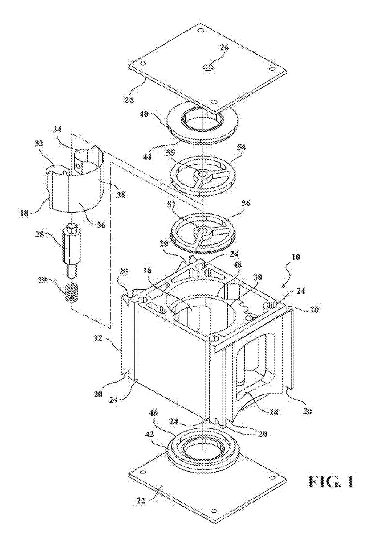
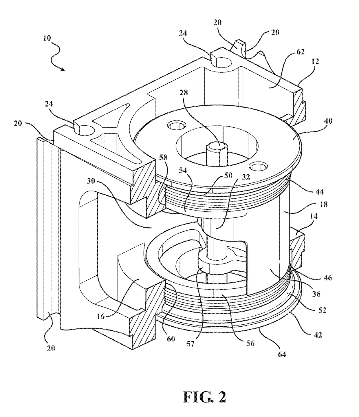
[0019]With reference now to the drawings, FIG. 1 shows an exemplary embodiment of a multifunction valve 10 according to the present disclosure, shown in an exploded view. The multifunction valve 10 includes a valve body 12 that can be installed into a fluid circuit to provide flow control. The valve body 12 facilitates fluid flow from an inlet 14 to an outlet 16. The rate of fluid flow through the valve body is modulated by a flow control gate 18 disposed in the valve body 10 and in the fluid flow pathway between the inlet 14 and the outlet 16.

[0020]The valve body 12 defines the structure of the multifunction valve, providing an enclosure to the fluid flow pathway secure against fluid leakage and enabling the multifunction valve to be integrated into a fluid circuit. The valve body 12 may be formed from a variety of materials appropriate to the intended function of the multifunction valve, including consideration of the choice of fluid media to be communicated and the operating pres...


PUM


Abstract

A multifunction valve includes a valve body defining an inlet, and outlet and an interior chamber. A flow control gate is disposed within the interior chamber and is rotatable through an arcuate range of positions relative to the outlet providing a high level of precision control of a fluid flow rate through the multifunction valve. A method of modulating a fluid flow rate includes directing fluid flow through a multifunction valve from an inlet to an outlet, the multifunction valve including a flow control gate, adjusting the flow rate through the multifunction valve by rotating a control shaft to position the flow control gate to variably occlude the outlet of the fluid control valve.

Description

RELATED APPLICATIONS[0001]This application claims priority to and the benefit of U.S. Provisional Patent Application No. 62 / 288,620, filed on Jan. 29, 2016, the entire contents of which are hereby incorporated by reference.BACKGROUND OF THE INVENTION[0002]1. Field of the Invention[0003]The present invention relates, generally, to fluid flow control and, more specifically, to a multifunction valve.[0004]2. Description of the Related Art[0005]Fluid control systems use a variety of valve types to turn fluid flow on and off, and also to modulate the flow rate through a fluid circuit. Conventional control systems may include valves having complex mechanisms including many components and complicated assembly. These valves may suffer from a lack of fine precision control, and require a larger volume within the fluid circuit.[0006]There remains a need for improved valves for use in fluid control systems that have a simple, compact design for a given maximum flow rate (flow rate of gas at wh...

Claims


Application Information

Patent Timeline
Patent Type & Authority Applications(United States)
IPC IPC(8): F16K5/04
CPCF16K5/0442F16K5/0407F16K5/103
Inventor MASEN, MARK GEOFFREYSAGOVAC, JASON
Owner MAXITROL
Learn More