
Cassette filter

a filter and cassette technology, applied in the field of cassette filters, can solve the problems of loss of filter properties, damage to the filter medium, and low resistance to mechanical stresses

Inactive Publication Date: 2005-07-28
CARL FREUDENBERG KG
View PDF7 Cites 0 Cited by
  • Summary
  • Abstract
  • Description
  • Claims
  • Application Information

AI Technical Summary

Benefits of technology

[0004] Therefore, the object of the present invention is to create a possibility with which the filter medium, i.e., the filter material, is protected from damage with the greatest of certainty. In addition, the product should be simple in design and assembly, should have a low weight, and should be inexpensive to manufacture.
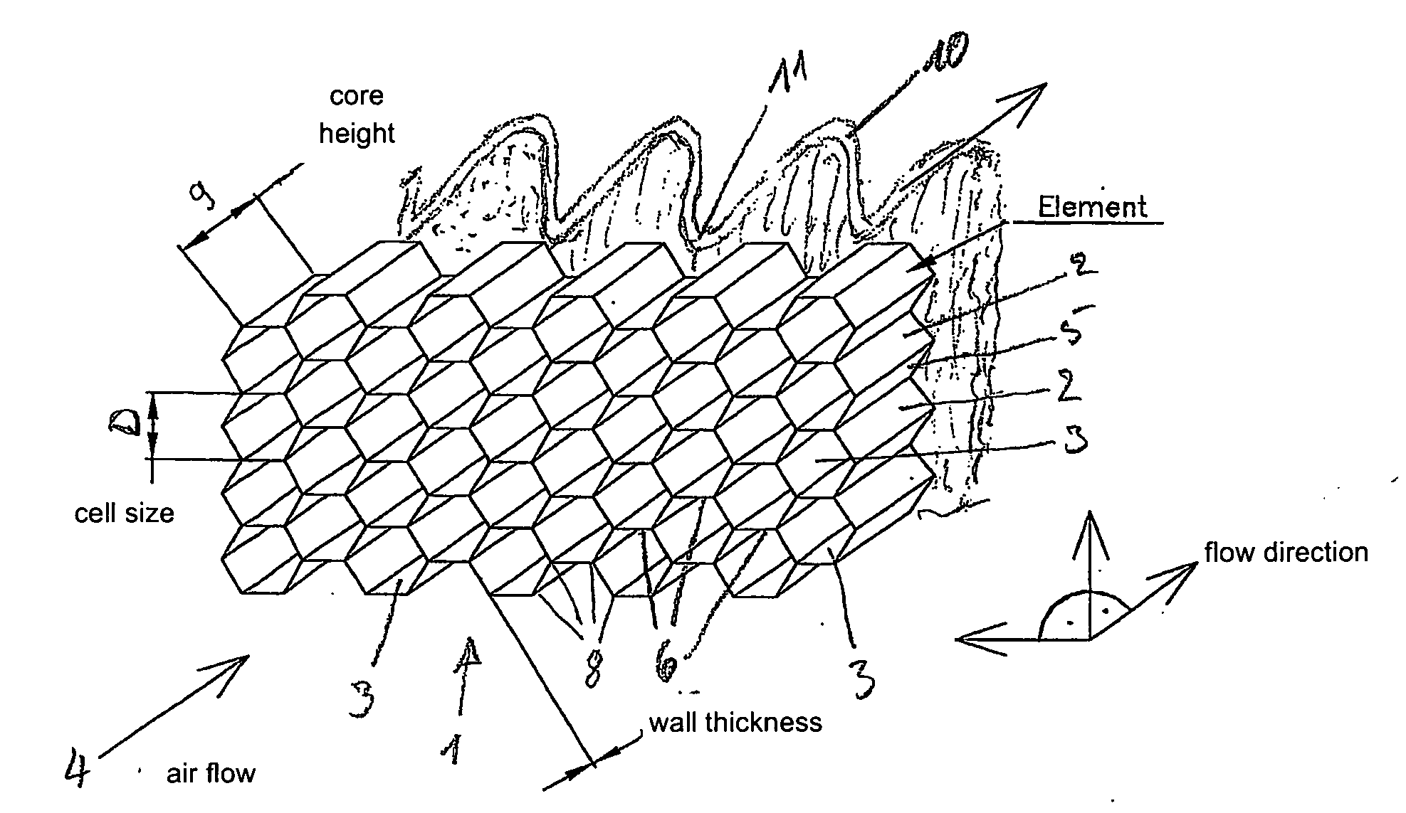
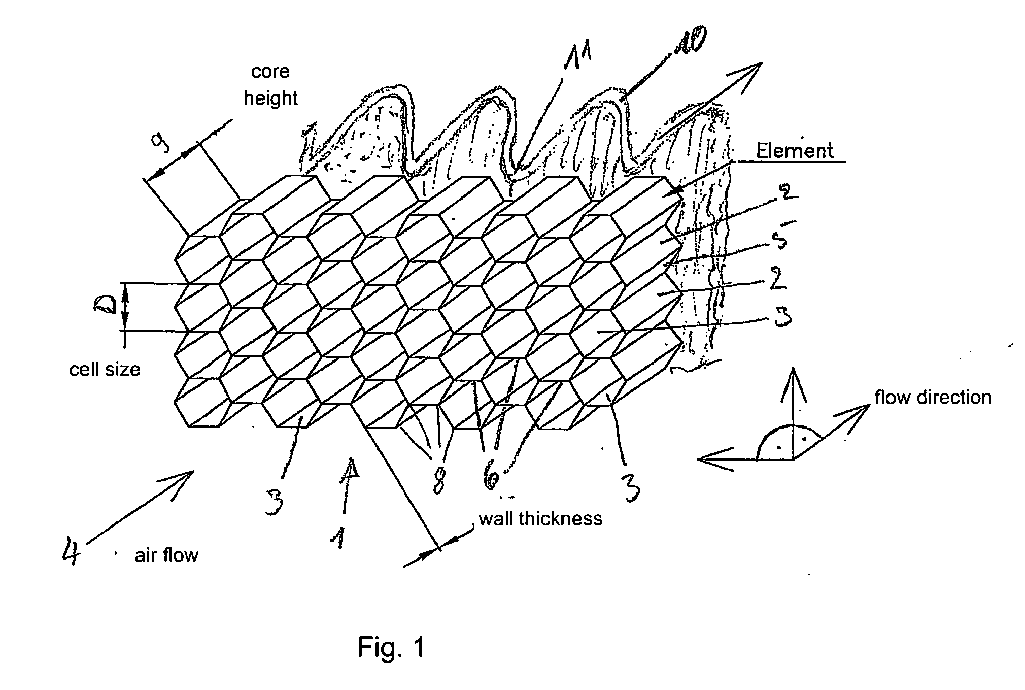
[0005] The means of achieving the object in a cassette filter of the type initially mentioned is provided according to the present invention, wherein the protective grid is composed of at least one film strip that is bent around the passage holes and extends parallel to the direction of oncoming flow of the medium to be filtered; the film strip repeatedly touches at least one other identically bent film strip outside of the passage holes at contact points and is glued to it at the contact points. A honeycomb-like structure is produced from the films, forming a protective grid of extremely high stability and strength.
[0008] To minimize the weight of the cassette filter, a thickness, i.e., core height, of 1 mm to 10 mm is selected for the protective grid. The honeycomb structure of the protective grid already yields high rigidity and strength with extremely small thicknesses.

Problems solved by technology

For example, glass fiber paper is used for filters of higher filter classes, but it has a very low resistance to mechanical stresses.
It tears easily, in particular when handled improperly, which results in damage to the filter medium, and thus to an impairment and possibly even to loss of the filter properties.
However, this material substantially increases the weight of the filter.
In addition, the material is not incinerable, i.e., it cannot be reduced to ashes.
However, experiments have shown that the rigidity of such grids is not sufficient to reliably prevent damage to the filter medium.

Method used


Image

  • Cassette filter
  • Cassette filter

Examples


Embodiment Construction

[0004] Therefore, the object of the present invention is to create a possibility with which the filter medium, i.e., the filter material, is protected from damage with the greatest of certainty. In addition, the product should be simple in design and assembly, should have a low weight, and should be inexpensive to manufacture.

[0005] The means of achieving the object in a cassette filter of the type initially mentioned is provided according to the present invention, wherein the protective grid is composed of at least one film strip that is bent around the passage holes and extends parallel to the direction of oncoming flow of the medium to be filtered; the film strip repeatedly touches at least one other identically bent film strip outside of the passage holes at contact points and is glued to it at the contact points. A honeycomb-like structure is produced from the films, forming a protective grid of extremely high stability and strength.

[0006] The film strips may have the shape o...


PUM

PropertyMeasurementUnit
Fractionaaaaaaaaaa
Thicknessaaaaaaaaaa
Diameteraaaaaaaaaa

Abstract

A cassette filter comprising a frame and a pleated filter material that is inserted therein, in addition to a protective grid having passage holes. The protective grid is fastened at a distance from the filter material in the frame and has a flow resistance that is smaller than that of the pleated filter material. The protective grid includes at least one film strip that is bent around the passage holes, said film strip extending parallel relative to the direction of flow of the medium to be filtered, and in that the protective grid recurrently contacts at least one other identically bent film strip outside the passage holes in contact points and is glued to said other film strip in the contact points.

Description

TECHNICAL FIELD [0001] The present invention relates to a cassette filter which has a frame and a pleated filter material that is inserted therein as well as a protective grid having passage holes, the protective grid being fastened in the frame at a distance from the filter material and having a flow resistance which is lower than that of the pleated filter material. BACKGROUND INFORMATION [0002] German Patent Document No. DE 195 45 064 A1 has already described a cassette filter which is used as a particulate filter and as a microfilter. Cassette filters of this type have proven successful in practice. Pleated filter mats such as those disclosed in German Patent Document No. DE 195 45 046 C2 are used as the filter medium. [0003] The filter media used with cassette filters are of various designs and material compositions. For example, glass fiber paper is used for filters of higher filter classes, but it has a very low resistance to mechanical stresses. It tears easily, in particula...

Claims


Application Information

Patent Timeline
IPC IPC(8): B01D29/07B01D46/00B01D46/10B01D46/52
CPCB01D29/07B01D2265/06B01D46/10B01D46/0043
Inventor TAPPER, RENATESCHROTH, THOMASCAESAR, THOMAS
Owner CARL FREUDENBERG KG
Learn More