Improvements relating to reinforcing structures for wind turbine blades

a technology of reinforcing structure and wind turbine blade, which is applied in the field of reinforcing structure, can solve the problems of increasing the likelihood of blade damage, affecting the integrity of the cured blade structure, and forming airlocks

Active Publication Date: 2017-08-03
VESTAS WIND SYST AS
View PDF7 Cites 25 Cited by
  • Summary
  • Abstract
  • Description
  • Claims
  • Application Information

AI Technical Summary

Benefits of technology

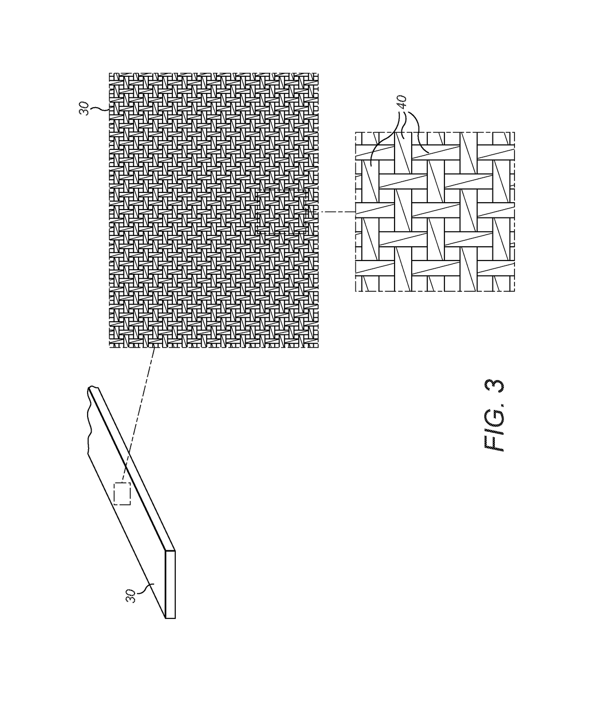
[0023]The infusion promoting layer may be selected such that the infusion speed of resin through the stack structure during a resin infusion process is compatible with the resin infusion speed through the plurality of blade components. This guards against voids, hollows and other infusion imperfections forming during the infusion process.

Problems solved by technology

However, larger blades experience increased forces during use which increases the likelihood of the blades suffering damage.
Problems that can become apparent are airlocks forming in parts of the layup through which the resin is unable to flow.
Sometimes, resin infiltrates through some parts of the layup more slowly than through other parts and this can also cause problems since the ‘wavefront’ of the resin flow can divert and travel along an unintended direction which can affect the integrity of the cured blade structure.

Method used


Image

  • Improvements relating to reinforcing structures for wind turbine blades
  • Improvements relating to reinforcing structures for wind turbine blades
  • Improvements relating to reinforcing structures for wind turbine blades

Examples


Embodiment Construction

[0033]FIG. 2 illustrates an elongate reinforcing structure 20 for a wind turbine blade. In the embodiments described below, the elongate reinforcing structure 20 is a spar cap like that described above with reference to FIG. 1 by way of introduction, and will be referred to as such from now on.

[0034]In FIG. 2 the spar cap 20 is shown on a larger scale so that its individual components can be seen more clearly. The spar cap 20 comprises a plurality of strips 22 of fibre-reinforced polymer arranged in alignment one on top of another in a stack structure 23 Each of the strips 22 extends longitudinally between opposed ends 24 (only one of which is shown in FIG. 2) and comprises opposite sides 26 and upper and lower surfaces 28, 29.

[0035]In principle, alternative forms of fibre-reinforced polymer, such as glass- or aramid-fibre based FRPs, may be used for the strips 22 although in practice carbon fibre is preferred for its particularly high strength characteristic. The strips 22 are fabr...


PUM

PropertyMeasurementUnit
thickaaaaaaaaaa
widthaaaaaaaaaa
widthaaaaaaaaaa

Abstract

A wind turbine blade including an elongate reinforcing structure, the reinforcing structure comprising a plurality of strips of fibre-reinforced polymer arranged into a stack structure, and at least one adjacent pair of the plurality of strips including an infusion promoting layer, wherein the infusion promoting layer is a fabric comprising a plurality of twisted yarns. The invention is also expressed as a method of assembling a wind turbine blade.

Description

FIELD OF THE INVENTION[0001]The present invention relates to wind turbine blades and particularly to a reinforcing structure such as a spar cap used within a wind turbine blade to provide the blade with additional strength and rigidity.BACKGROUND TO THE INVENTION[0002]The design of composite wind turbine blades is a compromise that strikes a balance between aerodynamic and structural priorities. The drive is now towards larger blades in order to maximise energy capture of the turbine installation. However, larger blades experience increased forces during use which increases the likelihood of the blades suffering damage.[0003]A modern utility-scale wind turbine blade comprises a structural beam that is typically formed from a two-part hollow shell. The blade is stiffened to prevent it from bending excessively and, usually, each shell incorporates one or more relatively stiff strips or ‘spars’ that run along the length of the blade. To provide the blade with the necessary strength to ...

Claims


Application Information

Patent Timeline
Patent Type & Authority Applications(United States)
IPC IPC(8): F03D1/06F03D13/00B29C70/42
CPCF03D1/0675B29C70/42B29L2031/085B29K2105/08F03D13/00B32B5/024B32B5/12B32B5/26F05B2280/6001B32B2603/00B32B2262/106B32B2262/101B32B2307/50B32B2307/718B32B2307/738B32B2250/42B32B2250/20B32B2260/02B32B2260/046B32B2262/0269B29C70/443B29C70/546Y02E10/72B29C70/84B32B17/04B32B27/12B32B2260/023B32B2305/07B32B2305/188B32B2305/10B32B2305/08B32B2305/18
Inventor CIESLAK, CHRISSPANDLEY, LUKE
Owner VESTAS WIND SYST AS
Why Eureka
Try Eureka