Electric brake system and method thereof

a technology of electric brakes and brake components, applied in the direction of brake systems, failure-safe aspects, braking components, etc., can solve the problem of not producing braking for

Active Publication Date: 2017-08-03
HL MANDO CORP
View PDF0 Cites 5 Cited by
  • Summary
  • Abstract
  • Description
  • Claims
  • Application Information

AI Technical Summary

Benefits of technology

This patent aims to prevent a situation where there is no braking force by detecting a failure in the hydraulic circuit in advance. The technical effect is the avoidance of dangerous situations.

Problems solved by technology

However, when a hydraulic circuit failure, such as a leak in the BC, occurs, there is a concern in that the HPU continuously generates a hydraulic pressure and supplies the hydraulic pressure to the master cylinder, and a dangerous situation in which a braking force is not generated due to lack of a brake fluid occurs when the pressure is exhausted.

Method used


Image

  • Electric brake system and method thereof
  • Electric brake system and method thereof
  • Electric brake system and method thereof

Examples


Embodiment Construction

[0039]Hereinafter, embodiments of the present disclosure will be described in detail with reference to the accompanying drawings. The present embodiments are provided in order to fully explain the spirit and scope of the present disclosure to those skilled in the art. Thus, the present disclosure is not to be construed as limited to the present embodiments set forth herein and may be embodied in other various forms. Parts irrelevant to the description are omitted in the drawings in order to clearly explain the present disclosure. Sizes of elements in the drawings may be exaggerated in order to facilitate understanding.

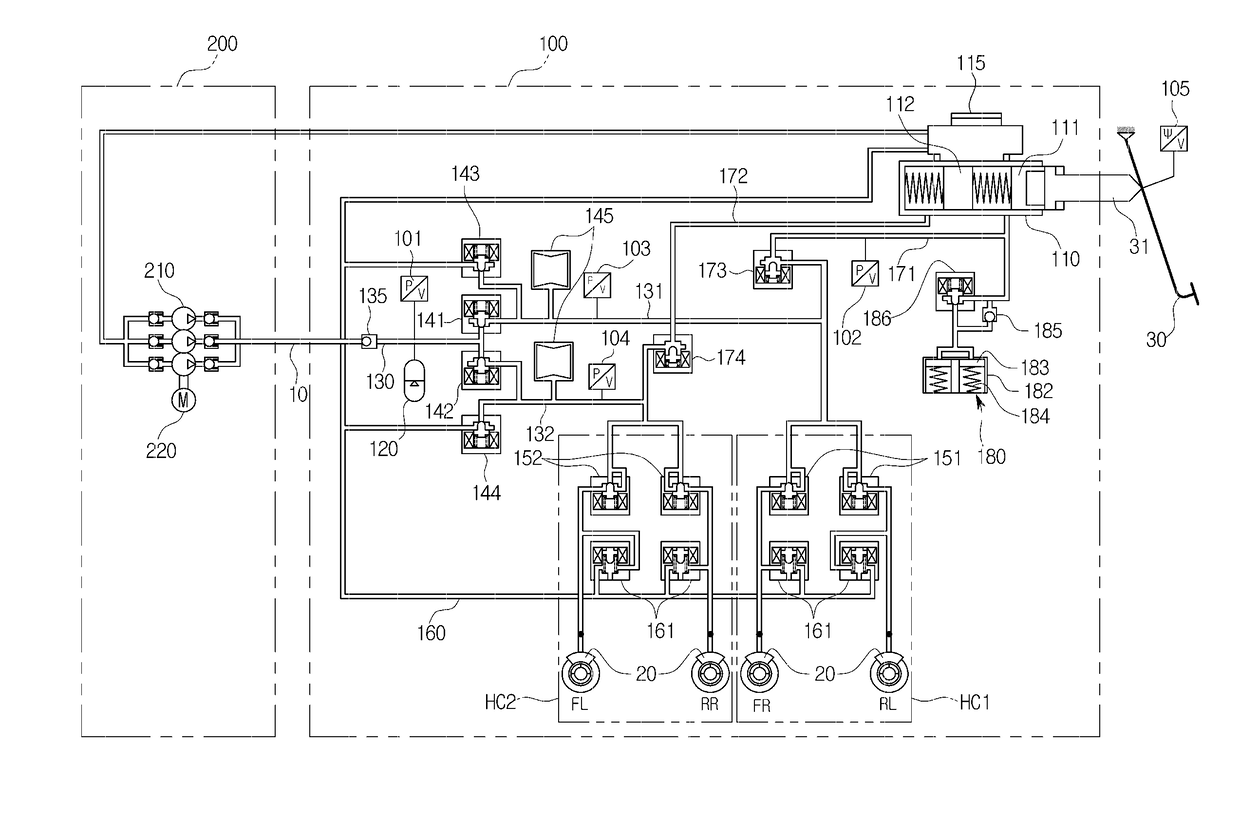
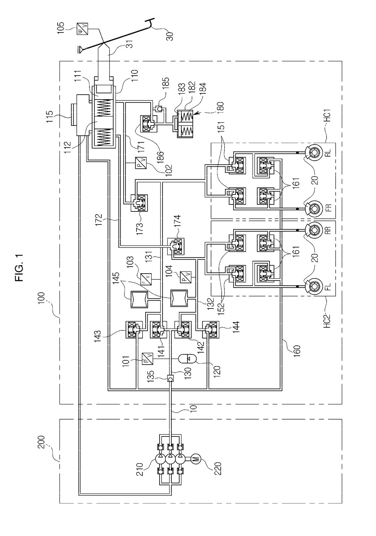
[0040]FIG. 1 is a view illustrating a hydraulic circuit diagram of an electronic brake system of a vehicle according to one embodiment of the present disclosure.

[0041]Referring to FIG. 1, an active hydraulic booster (AHB) system may be mainly divided into two units including a hydraulic pressure control system 100 and a power source unit 200.

[0042]The hydraulic pressur...


PUM


Abstract

Electronic brake system is disclosed. An electronic brake system includes, a pressure sensor including a first pressure sensor configured to measure a hydraulic pressure of the accumulator, a second pressure sensor configured to measure a hydraulic pressure of the first hydraulic circuit, and a third pressure sensor configured to measure a hydraulic pressure of the second hydraulic circuit, a driver including one or more apply valves and release valves configured to control the hydraulic pressures of the first hydraulic circuit and the second hydraulic circuit, a determiner configured to determine that at least one of the first hydraulic circuit and the second hydraulic circuit has failed when an absolute value of a slope of the pressure measured by the first pressure sensor is greater than a preset first threshold value and the pressure measured by the first pressure sensor is less than a preset second threshold value and a controller configured to close apply valves of the first hydraulic circuit and the second hydraulic circuit when the failure has been determined, determine that a leak has occurred in one of the first and second hydraulic circuits having an amount of pressure change greater than that of the other hydraulic circuit measured on the basis of the second pressure sensor and the third pressure sensor, and control braking using only the hydraulic circuit operating normally.

Description

CROSS-REFERENCE TO RELATED APPLICATION[0001]This application claims the benefit of Korean Patent Application No. 2016-0012835, filed on Feb. 2, 2016 in the Korean Intellectual Property Office, the disclosure of which is incorporated herein by reference.BACKGROUND[0002]1. Field[0003]Embodiments of the present disclosure relate to an electronic brake system, and more particularly, to an electronic brake system configured to perform in-circuit control for detecting a hydraulic circuit failure and preventing an accident and a control method thereof.[0004]2. Description of the Related Art[0005]Brake systems have to be installed for braking in vehicles, and recently, various types of systems have been proposed for obtaining more powerful and stable braking force.[0006]Examples of the brake systems are an anti-lock brake system (ABS) configured to prevent wheels from slipping during breaking, a brake traction control system (BTCS) configured to prevent driving wheels from slipping when veh...

Claims


Application Information

Patent Timeline
IPC IPC(8): B60T13/14B60T13/68B60T13/66B60T15/04B60T8/171B60T8/172
CPCB60T13/145B60T8/171B60T8/172B60T2270/403B60T15/045B60T13/686B60T13/662B60T13/16B60T13/745B60T17/22B60T2270/40B60T7/042B60T8/885B60T13/146
Inventor KIM, HAK-BURM
Owner HL MANDO CORP
Why Eureka
Try Eureka