
Aircraft frame structure and associated method

a frame structure and frame technology, applied in the field of aircraft frame structure, can solve the problems of increasing construction time, heavy structure, and complex manufacturing

Inactive Publication Date: 2017-07-27
AIRBUS OPERATIONS LTD
View PDF5 Cites 16 Cited by
  • Summary
  • Abstract
  • Description
  • Claims
  • Application Information

AI Technical Summary

Benefits of technology

The patent describes an aircraft frame structure that is resistant to impacts, such as from bird strikes or ground vehicles. The structure is made up of a water-resistant cover and an impact-resistant barrier made of shear thickening materials. The cover can be attached to the aircraft frame using a thermoplastic attachment means. The frame structure also includes a lightning strike dissipater to reduce the risk of electrical arcing. The technical effects of this invention are to provide a lightweight and impact-resistant aircraft frame structure, with additional protection against water damage and lightning strike.

Problems solved by technology

Such structures can be heavy and may be complex to manufacture (for example, in the case of some supporting elements made from composite materials).
The use of many bolts may lead to an increase in construction time and may provide many points at which lightning may strike an aircraft.

Method used


Image

  • Aircraft frame structure and associated method
  • Aircraft frame structure and associated method
  • Aircraft frame structure and associated method

Examples


Embodiment Construction

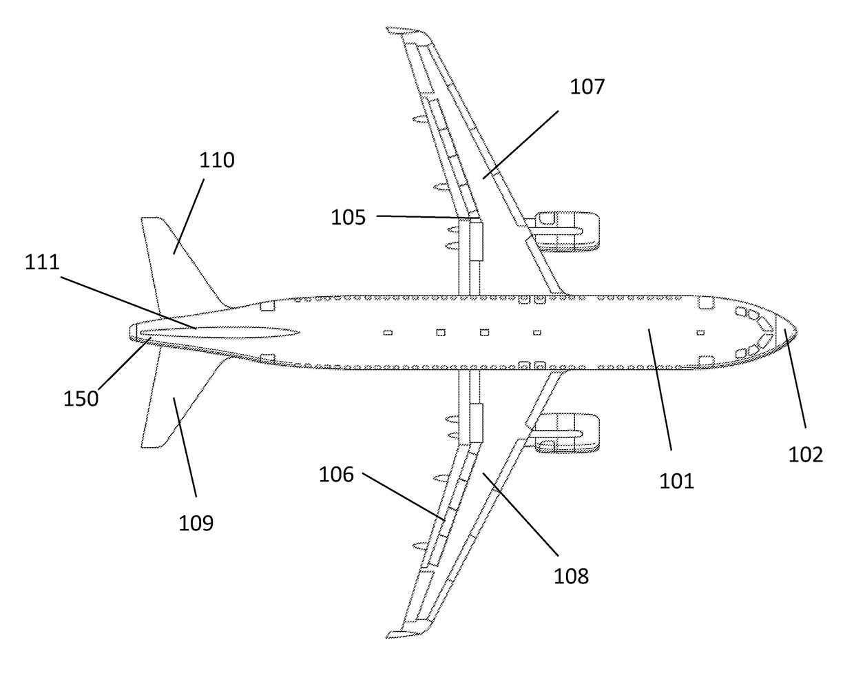
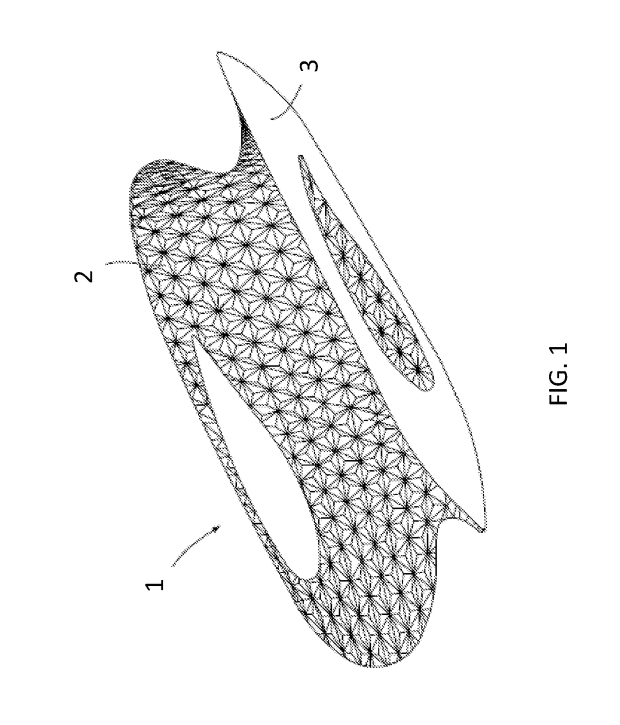
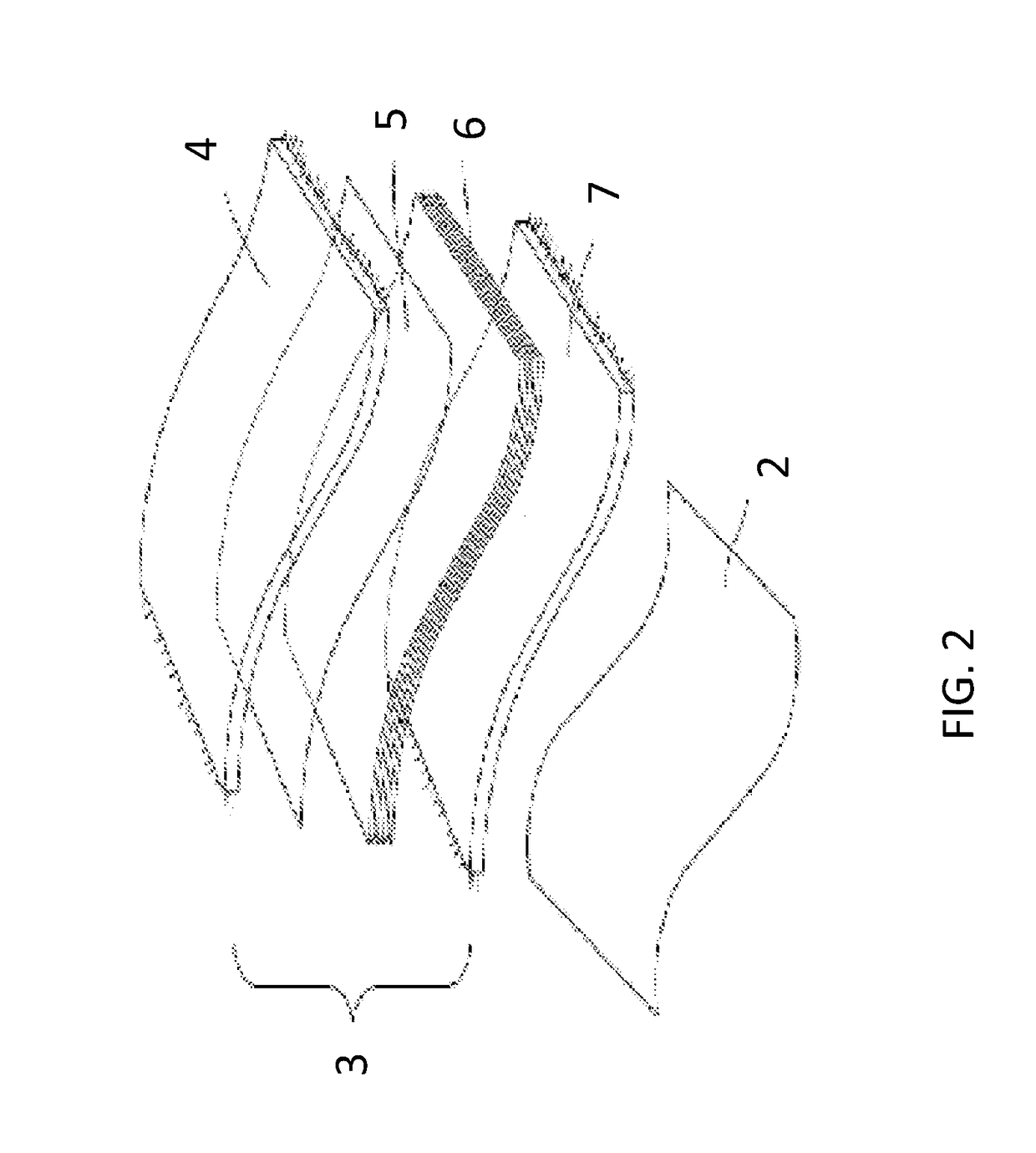
[0042]A belly fairing comprising an aircraft frame structure according to an example of an embodiment of the invention will now be described with reference to FIGS. 1 and 2. The belly fairing is denoted generally be reference numeral 1, and comprises a grid support 2 in the form of a geodetic support and an overlying laminate 3. In use, the laminate 3 is located on the outside of the aircraft. The grid support 2 may be made in any suitable manner as will be known to those skilled in the art of airframe construction, such geodetic supports being used in the airframes of the Vickers-Armstrong Wellesley, Wellington, Windsor and Warwick aircraft of the 1930s and 1940s, and as described in “Geodetic Aircraft Structure” by K. D. Powell, Sports Aviation, 1961, pages 17-24. For example, the geodetic support 2 may be formed from a network of aluminium alloy channel-beams, as was used for the Vickers-Armstrong Warwick aircraft. The grid support 2 is lightweight and strong, and if there is loc...


PUM

PropertyMeasurementUnit
water-resistantaaaaaaaaaa
water-resilientaaaaaaaaaa
water-resilient elastically-deformableaaaaaaaaaa

Abstract

An aircraft frame structure including a grid support (such as a geodetic support) (2) and (i) an impact-resistant barrier (6) including a shear thickening fluid, and (ii) a water-resistant, elastically-deformable cover (4). Methods to make and repair an aircraft using the aircraft frame structure.

Description

BACKGROUND OF THE INVENTION[0001]The present disclosure relates to an aircraft frame structure, and more specifically to an aircraft frame structure comprising a grid support, such as a geodetic support.[0002]The present invention concerns an aircraft frame structure. More particularly, but not exclusively, this invention concerns an aircraft frame structure comprising grid support, such as a geodetic support. The invention also concerns a method of making an aircraft frame structure, a laminate for making an aircraft frame structure, a method of repairing or maintaining an aircraft, an aircraft component and an aircraft.[0003]Conventional modern aircraft structures typically comprise a “skin” of aluminium alloy supported by frames, stringers, spars, webs and the like. Such structures can be heavy and may be complex to manufacture (for example, in the case of some supporting elements made from composite materials). Furthermore, such conventional structures sometimes require the use ...

Claims


Application Information

Patent Timeline
Patent Type & Authority Applications(United States)
IPC IPC(8): B64C1/12B32B7/04B32B43/00B64C1/08B64C3/26
CPCB64C1/12B64C1/08B64C3/26B32B43/00B32B2605/18B64C2001/0072B32B2307/51B32B2307/56B32B2274/00B32B7/045Y02T50/40B32B7/05
Inventor TOTHILL, GUYADDA, LAIDLANGLEY, ANTHONY
Owner AIRBUS OPERATIONS LTD
Learn More