
Configurable platform

a platform and platform technology, applied in the field of medical imaging, can solve the problems of inability to achieve the desired effect, inability to achieve adequate solutions, and inability to meet the requirements of operation, etc., and achieve the effect of reducing the image size of fluorescent ligh

Active Publication Date: 2017-07-27
STRYKER EUROPEAN OPERATIONS LIMITED
View PDF19 Cites 85 Cited by
  • Summary
  • Abstract
  • Description
  • Claims
  • Application Information

AI Technical Summary

Benefits of technology

The patent text describes variations of fluorescence imaging systems for observing objects. These systems use white light and multiple excitation light wavelengths to cause the object to emit fluorescent light. The light is then captured on an image sensor, which sends a signal to an image processor for further analysis. The technical effect of the patent text is to provide a system that can capture images with high sensitivity and resolution using fluorescence imaging techniques. Another variation described in the patent text is a method for using a beam splitter to separate the fluorescence light from the reflected white light, allowing for more accurate imaging. Overall, these variations provide an improved tool for studying fluorescence-based processes in biological and medical applications.

Problems solved by technology

Some limitations of intraoperative fluorescence imaging devices that are configured for use in specific surgeries have been recognized by others, but previous attempts at generating an adequate solution have fallen short of the desired outcome.
However, because the original product architecture for such devices was established without consideration of the new surgical application, such attempted adaptation may result in an unacceptable compromise in performance, functionality and ergonomics.
Furthermore, many optical imaging devices appear to detect only a single fluorescence excitation and emission waveband, and consequently are limited to use with only the particular fluorophores utilizing that single excitation / emission waveband.
However, these devices are too large and cumbersome for use in many surgical applications.

Method used


Image

  • Configurable platform
  • Configurable platform
  • Configurable platform

Examples


Embodiment Construction

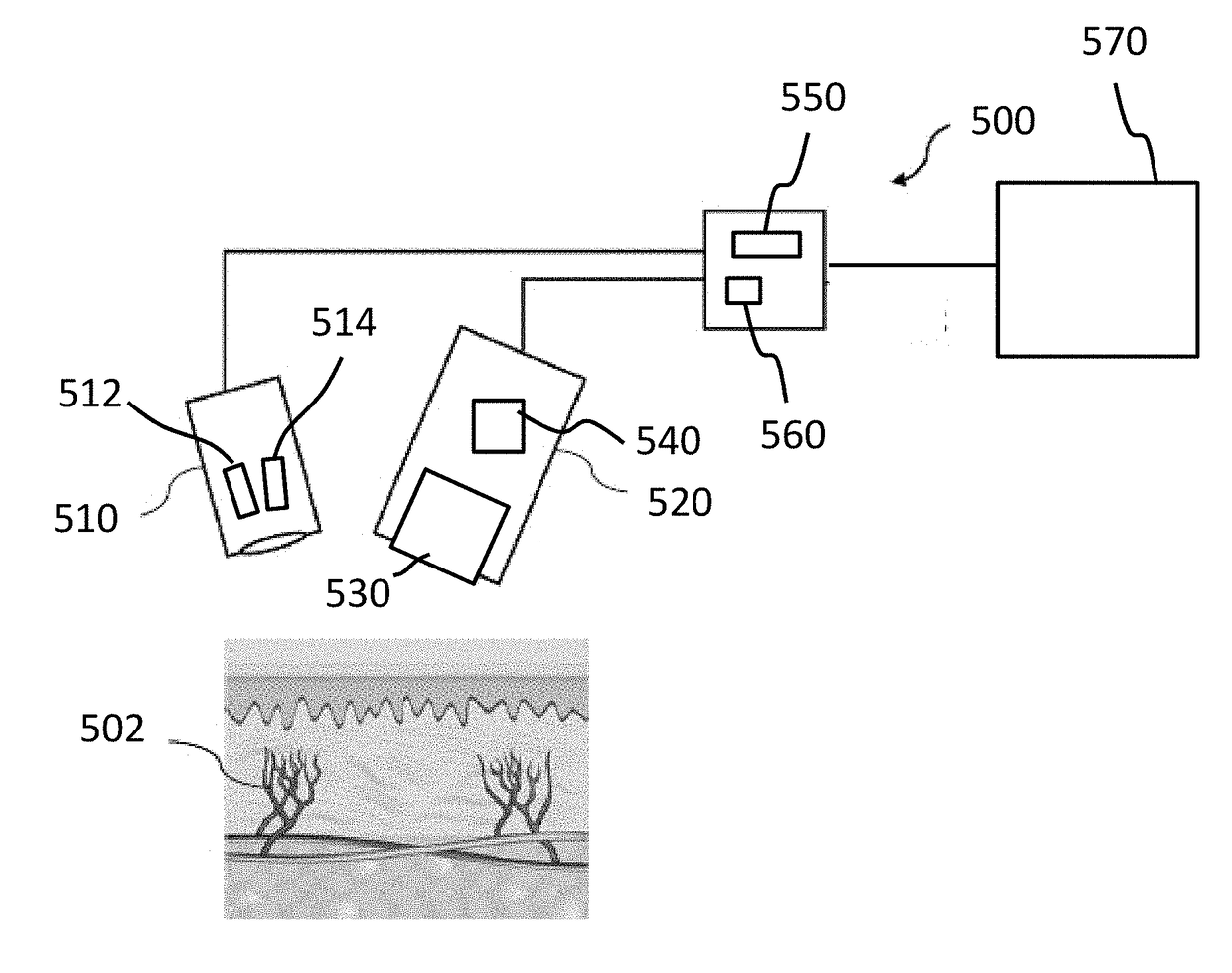
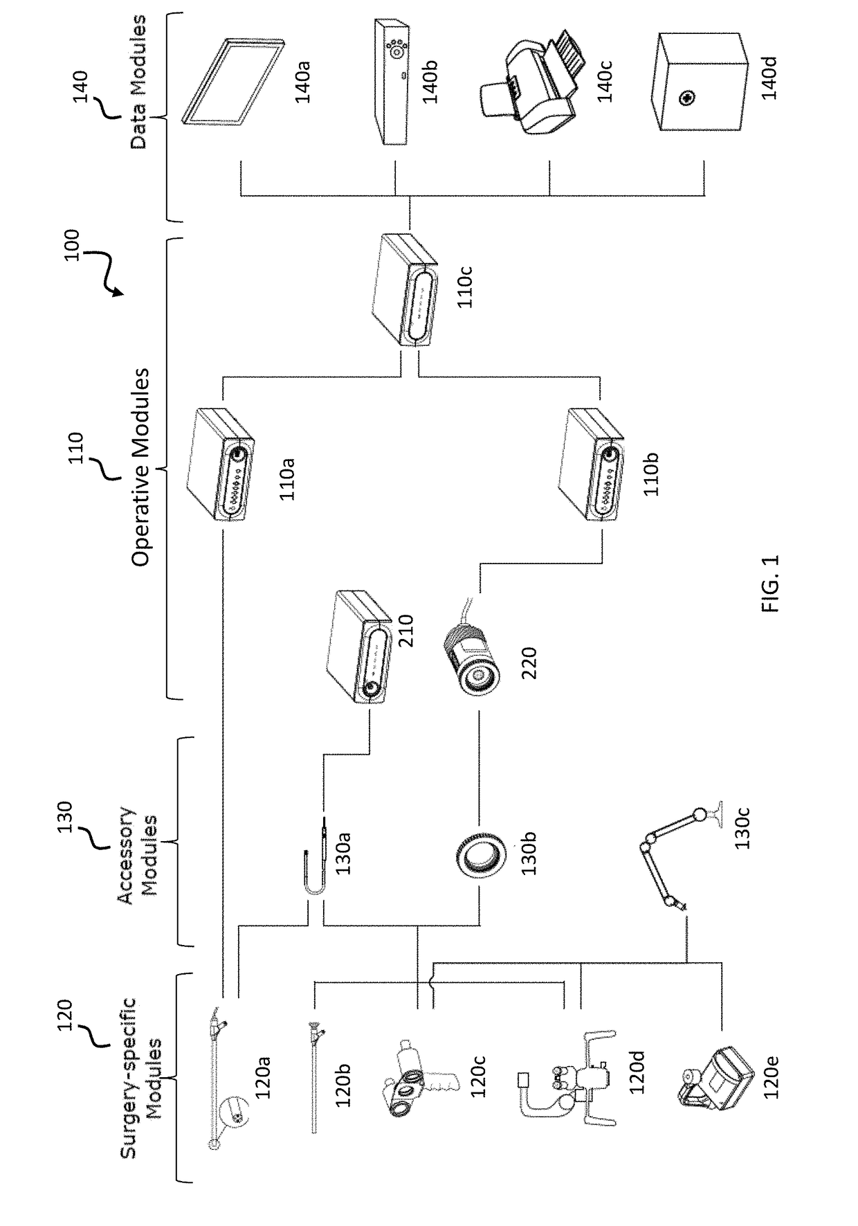
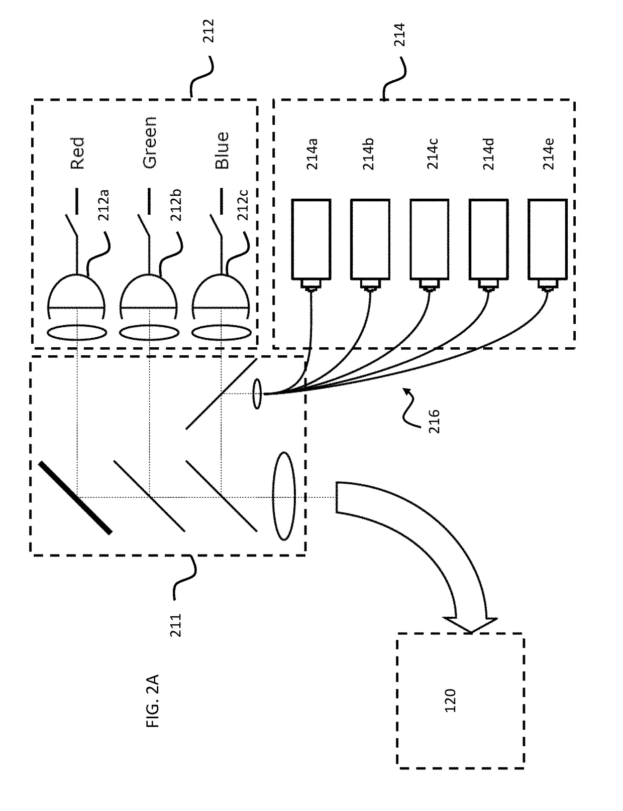
[0061]Reference will now be made in detail to implementations and variations of the invention, examples of which are illustrated in the accompanying drawings. Various fluorescence imaging systems, methods, imaging agents, and kits are described herein. Although at least two variations of imaging systems, methods (e.g., fluorescence imaging system and method with a configurable platform and multiplexed fluorescence imaging system and method), imaging agents, and kits are described, other variations of fluorescence imaging systems, methods, imaging agents, and kits may include aspects of the systems, methods, imaging agents, and kits described herein combined in any suitable manner having combinations of all or some of the aspects described.

[0062]The various systems and methods may be used for imaging an object. The object may, for example, include tissue (e.g., tissue having one or more endogenous or exogenously-introduced fluorophores), but may additionally or alternatively include ...


PUM


Abstract

A fluorescence imaging system for imaging an object, the system includes a white light provider that emits white light, an excitation light provider that emits excitation light in a plurality of excitation wavebands for causing the object to emit fluorescent light, a component that directs the white light and excitation light to the object and collects reflected white light and emitted fluorescent light from the object, a filter that blocks light in the excitation wavebands and transmits at least a portion of the reflected white light and fluorescent light, and an image sensor assembly that receives the transmitted reflected white light and the fluorescent light.

Description

REFERENCE TO RELATED APPLICATIONS[0001]This application claims priority to U.S. Provisional Application Ser. No. 62 / 354,611, filed Jun. 24, 2016, titled “Configurable Platform,” and to U.S. Provisional Application Ser. No. 62 / 287,415, filed Jan. 26, 2016, titled “Configurable Platform,” which are hereby incorporated by reference in their entirety.FIELD OF THE INVENTION[0002]The present disclosure relates generally to medical imaging, and more particularly to the acquiring and processing of medical images for visualizing tissue of a subject.BACKGROUND OF THE INVENTION[0003]Many forms of intraoperative optical imaging are used in surgical applications, and such uses are continuing to expand. One area of particular growth involves imaging systems that excite and image fluorescence emitted by endogenous or exogenously introduced fluorophores. Fluorescence imaging capabilities have consequently been incorporated into a variety of highly specialized imaging equipment tailored for particul...

Claims


Application Information

Patent Timeline
IPC IPC(8): A61B5/00H04N5/238A61B1/313H04N5/232A61B1/04H04N9/097G02B27/10
CPCA61B5/0071H04N9/097H04N5/238A61B1/3132H04N5/23245A61B1/043G02B27/1013A61B5/0084H04N2209/049A61B5/0035H04N13/204A61B1/00186A61B1/051A61B1/0638A61B1/0684G02B21/16G01J3/0248G01J1/58G01J3/0205G01J3/021G01J3/10G01J3/36G01J3/4406G01J3/0208G02B27/106H04N23/56H04N23/60H04N23/667H04N23/75H04N23/11H04N23/74H04N25/11H04N23/16G01J1/00
Inventor FENGLER, JOHN JOSEF PAULSTEAD, ROBERT ANTHONY
Owner STRYKER EUROPEAN OPERATIONS LIMITED
Learn More