
Display controlling method and electronic device adapted to the same

a technology of electronic devices and control methods, applied in the direction of static indicating devices, instruments, portable computer details, etc., can solve problems such as difficulty in controlling the brightness of the screen

Active Publication Date: 2017-07-20
SAMSUNG ELECTRONICS CO LTD
View PDF17 Cites 32 Cited by
  • Summary
  • Abstract
  • Description
  • Claims
  • Application Information

AI Technical Summary

Benefits of technology

The present disclosure is related to electronic devices with screens that can be controlled using an illuminance sensor and an angle sensor. The disclosure aims to enable electronic devices to measure the angle between the screens and control the brightness based on the measured angle. Additionally, the disclosure provides a solution for electronic devices with foldable housings that allows for the measurement of the angle between the screens when the screens are folded in different directions. Overall, the patent text provides various functions and improvements for electronic devices with multiple screens that can be controlled using one sensor and an angle sensor.

Problems solved by technology

However, prior art methods adjust the brightness of a screen of an electronic device using an illuminance sensor built in the electronic device, without considering whether a screen of the electronic device is covered with a cover or by another screen of the electronic device.
As such, when the electronic device is covered with a cover or another screen, the electronic device always considers the device to be in a dark environment regardless of the brightness of the outside environment and, thus, has difficulty controlling the brightness of the screen.
This problem may also occur in electronic devices which include a hall sensor or a geomagnetic sensor for detecting the change in magnetic fields when the brightness of the screen is adjusted via the hall sensor or the geomagnetic sensor.

Method used


Image

  • Display controlling method and electronic device adapted to the same
  • Display controlling method and electronic device adapted to the same
  • Display controlling method and electronic device adapted to the same

Examples


Embodiment Construction

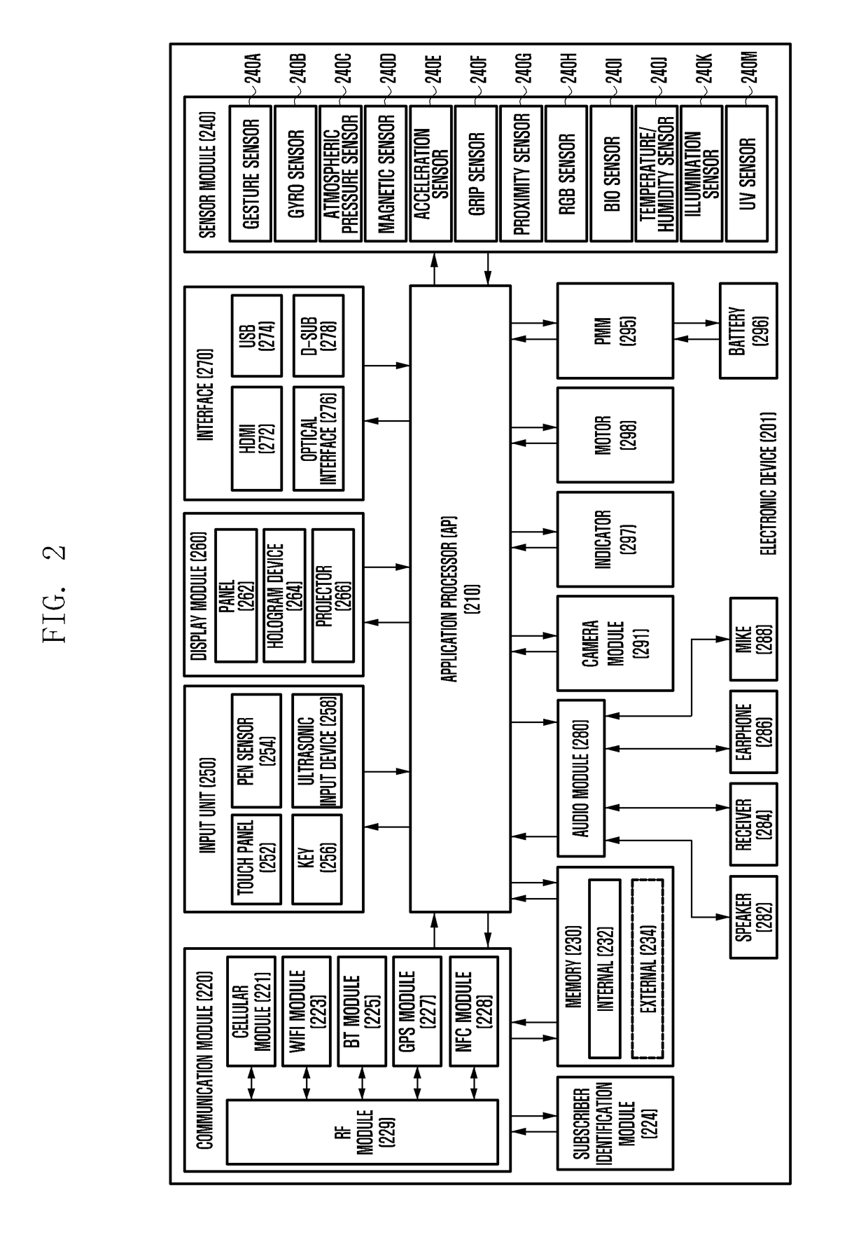
[0026]Hereinafter, the present disclosure is described in detail with reference to the accompanying drawings. While the present disclosure may be embodied in many different forms, specific embodiments of the present disclosure are shown in the drawings and are described herein in detail, with the understanding that the present disclosure is to be considered illustrative of the principles of the disclosure and is not intended to limit the disclosure to the specific embodiments illustrated. The same reference numbers are used throughout the drawings to refer to the same or like parts.

[0027]As used herein, the expression“comprise” indicates the presence of a corresponding function, operation, or element and does not limit additional functions, operations, or elements. Further, the term “have” indicates the presence of a characteristic, numeral, step, operation, element, component, or combination thereof and does not exclude the presence or addition of other characteristics, numerals, s...


PUM


Abstract

An electronic device is provided. The electronic device includes a foldable housing. The foldable housing includes a first housing including a first display and an illuminance sensor on a front surface, and a second housing, adjacent to the first housing, including a hole formed through a front surface and a rear surface of the second housing. The front surface of the first housing faces the front surface of the second housing when the second housing is folded in a first direction with respect to the first housing, and a rear surface of the first housing faces the rear surface of the second housing when the second housing is folded in a second direction with respect to the first housing.

Description

PRIORITY[0001]The present application claims priority under 35 U.S.C. §119(a) to a Korean Patent Application filed on Jan. 14, 2016, in the Korean Intellectual Property Office and assigned Ser. No. 10-2016-0004783, the entire disclosure of which is incorporated herein by reference.BACKGROUND[0002]1. Field of the Disclosure[0003]The present disclosure relates generally to a display controlling method and an electronic device adapted to the method.[0004]2. Description of the Related Art[0005]Various electronic devices are equipped with two or more displays, which are physically separated from each other, to output a screen on each of the displays. Further, in recent years, various electronic devices have been developed to output multiple screens on a single display (e.g., a flexible display) in such a way that the display is functionally split into a corresponding number of screens.[0006]However, prior art methods adjust the brightness of a screen of an electronic device using an illu...

Claims


Application Information

Patent Timeline
IPC IPC(8): G06F3/14G06F3/0346G06F1/16G09G5/10
CPCG09G2360/144G09G2330/021G06F3/1423G09G5/10G09G2380/02G06F1/1618G06F1/166G09G2320/0646G06F3/0346G06F1/1641G06F1/1647G06F1/1652G06F1/1677G06F1/3215G06F1/3265G06F2200/1634G09G2320/0626Y02D10/00G09G3/035B41F15/14B41F15/34B41F15/42B41F15/44B41M1/12B41P2215/10
Inventor CHOI, SEUNGKILEE, SEUNGHOONKIM, KYUNGJUNG
Owner SAMSUNG ELECTRONICS CO LTD
Learn More