Operating method for a vehicle drive train of a working machine including a drive motor, a transmission and an output

Active Publication Date: 2017-07-20
ZF FRIEDRICHSHAFEN AG
View PDF0 Cites 1 Cited by
  • Summary
  • Abstract
  • Description
  • Claims
  • Application Information

AI Technical Summary

Benefits of technology

The present invention provides a method to set the speed of a motor in a way that adjusting the transmission ratio can achieve high speeds with minimal effort. This is useful when there is a high power demand on the motor during operation.

Problems solved by technology

In general, if the rotational speed level of the drive motor is reduced at the same time that a high transmission ratio is set in the area of a CVT transmission in order to reduce the fuel consumption, then during unfavorable variations of the operating condition of a working machine, during which a driver only calls for a low vehicle speed but by virtue of a working hydraulic system the working machine is trying to generate a lot of power, in some circumstances the drive motor cannot produce sufficient drive power for this.
In order by means of the drive motor to make sufficient drive power available for this, the drive motor must be operated at a correspondingly high rotational speed, but this cannot be done to the extent desired by the procedures known until now.

Method used


Image

  • Operating method for a vehicle drive train of a working machine including a drive motor, a transmission and an output
  • Operating method for a vehicle drive train of a working machine including a drive motor, a transmission and an output
  • Operating method for a vehicle drive train of a working machine including a drive motor, a transmission and an output

Examples


Embodiment Construction

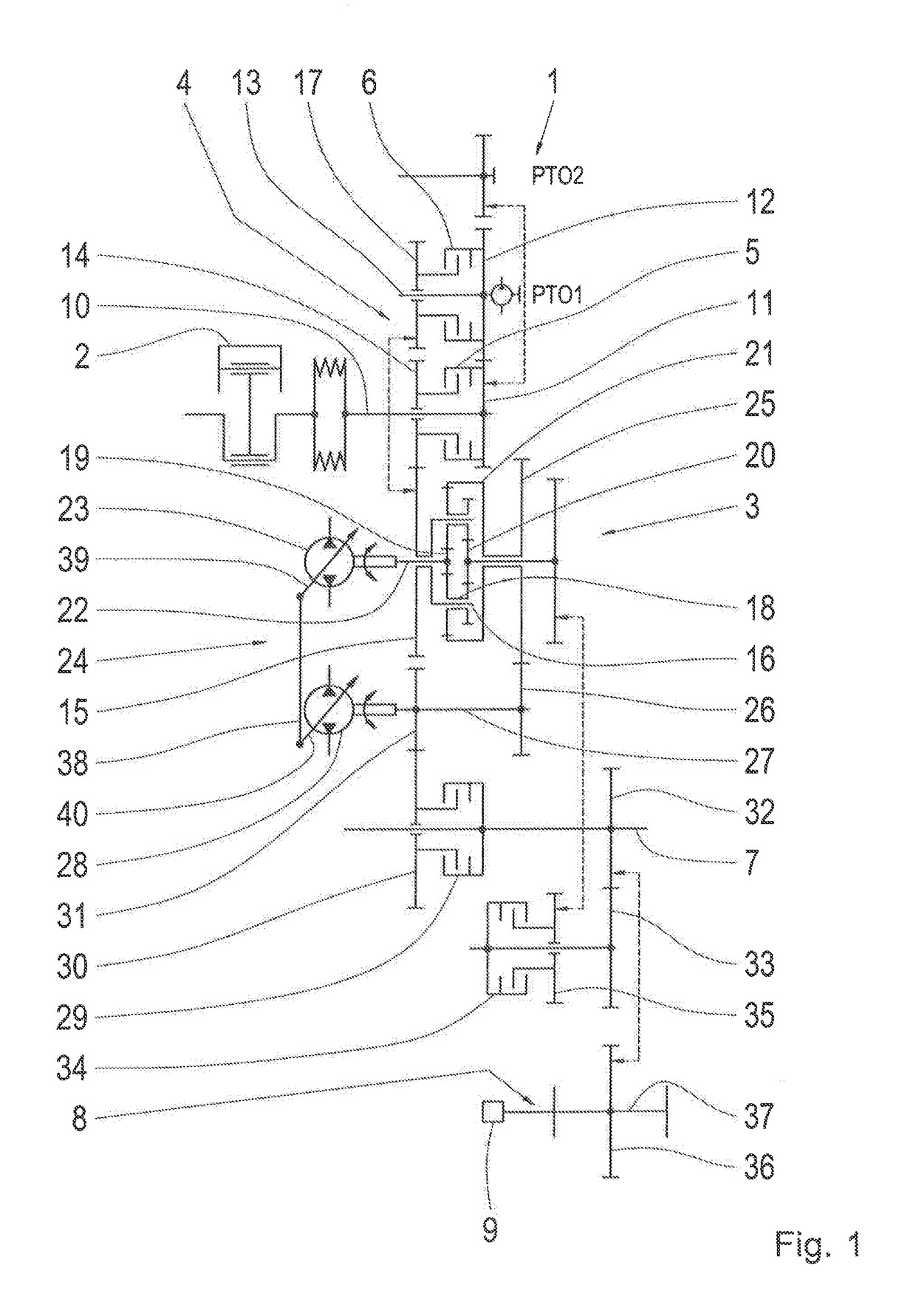
[0035]FIG. 1 shows a schematic representation of a vehicle drive-train 1 comprising a drive motor 2 and a continuously variable, power-split automatic transmission 3 that can be coupled thereto. In the present case the drive motor 2 is in the form of an internal combustion engine, preferably a Diesel engine, and in other embodiments the vehicle drive-train 1 can be in the form of an electric machine or a combination of an internal combustion engine of any type with an electric machine.

[0036]Between the drive motor 2 and the transmission or automatic transmission 3 in this case a reversing transmission 4 is provided, which comprises two frictional shifting elements 5, 6 each designed as a travel direction clutch. Thus, a drive input rotational movement of the drive motor 2 when the frictional shifting element 5 is closed, is passed on to the transmission 3 with a rotational direction such that a working machine built with the drive-train 1 is propelled in the forward travel direction...


PUM


Abstract

A method for the operation of a vehicle drive-train of a working machine having a drive motor, a transmission whose transmission ratio can be varied continuously, and a drive output. A rotational speed (nmot) of the drive motor can be varied by the driver, by the driver's actuation of a first control element (50), within a rotational speed range (53) delimited by an upper characteristic line (nmoto) and a lower characteristic line (nmotu). The characteristic lines (nmoto, nmotu) are functions of a reciprocal transmission ratio (irez) of the transmission. Furthermore, the rotational speed (nmot1) of the drive motor that can be set by the driver by way of the first control element (50), can be influenced by the driver's actuation of a second control element (51) and as a function of an operating condition of the working machine.

Description

[0001]This application claims priority from German patent application serial no. 10 2016 200 336.4 filed Jan. 14, 2016.FIELD OF THE INVENTION[0002]The invention concerns a method for operating a vehicle drive-train of a working machine, having a drive motor, a transmission with a transmission ratio that is continuously variable and a drive output.BACKGROUND OF THE INVENTION[0003]U.S. Pat. No. 8,585,543 B1 describes a system and a method for controlling the speed of a working machine, which comprises a continuous transmission, namely a so-termed CVT (continuously variable transmission) which is functionally connected to a drive source. Associated with the CVT are a number of selectable virtual gear steps. The working machine comprises a machine operator's input device which can produce a machine operator's input signal that specifies a desired setting of the basic speed of the working machine. The machine operator's input signal can be converted to a CVT rotational speed command and ...

Claims


Application Information

Patent Timeline
IPC IPC(8): B60W30/188F02D29/02F02D31/00F16H63/50
CPCB60W30/1882F16H63/50F02D29/02F02D2200/602F02D2200/101F02D2200/502F02D31/001B60W30/188F16H61/475F02D41/0225F02D2200/60F02D2400/12B60W30/18063B60W2510/1005B60W2540/10B60W2710/0644B60W10/103B60W10/06
Inventor HIEMER, MARCUSKUHN, JAN-FREDERIKSCHINACHER, STEPHANBIEBER, SVENLEGNER, JURGEN
Owner ZF FRIEDRICHSHAFEN AG
Why Eureka
Try Eureka