
Techniques for positioning energy infrastructure

a technology for positioning energy infrastructure and infrastructure, applied in the field of energy development, can solve the problems of overwhelming access roads and gathering pipelines, difficult to determine the placement of energy infrastructure, and large volume of visualizing and managing

Inactive Publication Date: 2017-07-13
NATURE CONSERVANCY THE
View PDF2 Cites 1 Cited by
  • Summary
  • Abstract
  • Description
  • Claims
  • Application Information

AI Technical Summary

Benefits of technology

This patent describes a system that helps users create optimized layouts for oil and gas wells. The system takes into account factors like cost and environmental impact and provides a visual representation of the layout through a map representation. Users can customize different parameters and the system combines user input and base data to come up with alternative layouts and associated metrics. The technical effect of this system is that it streamlines the design process for oil and gas wells and allows users to create more efficient and cost-effective layouts while balancing environmental impact.

Problems solved by technology

Determining appropriate placement of energy infrastructure can often be challenging.
However, visualizing and managing this large volume of information to determine an appropriate placement of drilling pads for petroleum wells, and related access roads and gathering pipelines can be overwhelming.
For example, it is difficult for a user to easily visualize layouts that have minimal environmental impact and optimized impact / cost tradeoff, particularly when planning multiple well pads at the same time.
In view of the foregoing, there may be significant problems and shortcomings associated with traditional techniques for determining the appropriate placement of energy infrastructure, including, for example, petroleum well pads, and access roads and gathering pipelines.

Method used


Image

  • Techniques for positioning energy infrastructure
  • Techniques for positioning energy infrastructure
  • Techniques for positioning energy infrastructure

Examples


Embodiment Construction

[0029]In some embodiments, techniques disclosed herein enable a user to input various factors to be considered when selecting the placement of a drilling pad for oil and gas wells and associated access roads and gathering pipelines. The alternative placements may be represented to the user in a map representation with associated metrics. Various steps and factors for user input, as well as alternative placements as output will be described in further detail.

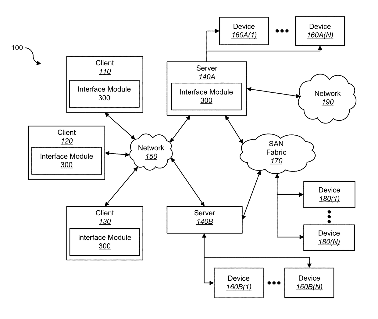
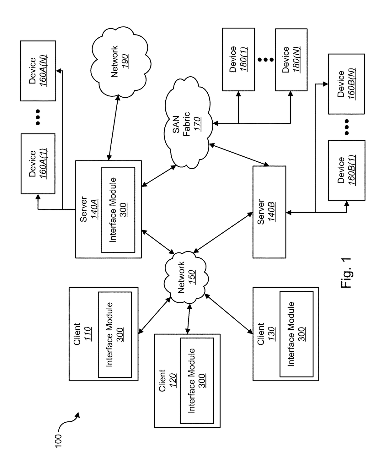
[0030]FIG. 1 shows a block diagram depicting a network architecture 100 in accordance with an embodiment of the present disclosure. FIG. 1 is a simplified view of network architecture 100, which may include additional elements that are not depicted, but that are well known to one skilled in the art. Network architecture 100 may contain client systems 110, 120 and 130, as well as servers 140A-140N (one or more of each of which may be implemented using computer system 200 shown in FIG. 2). Client systems 110, 120 and 130 may be com...


PUM


Abstract

Techniques for positioning energy infrastructure such as petroleum well pads, and related access roads and gathering pipelines are disclosed. In one embodiment, a system for positioning energy infrastructure comprises one or more processors. The one or more computer processors are configured to receive user input. The user input comprises a boundary where energy infrastructure is placed within and additional features to consider when positioning energy infrastructure. The one or more processors are further configured to store, in a shareable format, a plurality of layouts for the energy infrastructure and associated metrics and parameters based on the user input and base datasets. The base datasets comprise spatial datasets. The base datasets may also comprise default values for input parameters. The one or more processors are further configured to output, on a display device, the plurality of layouts for the energy infrastructure and the associated metrics and parameters.

Description

RELATED APPLICATIONS[0001]This application claims priority to U.S. Provisional Patent Application No. 62 / 276,304, filed Jan. 8, 2016, which is hereby incorporated by reference herein in its entirety.FIELD OF THE DISCLOSURE[0002]The present disclosure relates generally to energy development and, more particularly, to techniques for determining the placement of energy infrastructure.BACKGROUND OF THE DISCLOSURE[0003]Determining appropriate placement of energy infrastructure can often be challenging. For example, various factors must be considered when selecting the placement of a drilling pad for petroleum wells. Sufficient access to the reservoir (i.e., an underground pocket of gas and / or oil) must be achieved while also taking into consideration the state of the surface topology and terrain around the reservoir such as existing infrastructure, forests, and wetlands. However, visualizing and managing this large volume of information to determine an appropriate placement of drilling p...

Claims


Application Information

Patent Timeline
IPC IPC(8): G06Q10/06G06Q50/26G06Q50/06
CPCG06Q10/06313G06Q50/26G06Q50/06
Inventor JOHNSON NelsGAGNOLET TamaraMINNEY Thomas
Owner NATURE CONSERVANCY THE
Learn More