Tubes and manifolds for heat exchangers

Active Publication Date: 2017-07-13
HAMILTON SUNDSTRAND CORP
View PDF0 Cites 0 Cited by
  • Summary
  • Abstract
  • Description
  • Claims
  • Application Information

AI Technical Summary

Benefits of technology

The patent describes a design for a manifold with multiple tubes that have separate openings inside the manifold and different offsets from each other. The offsets can vary based on the angle of the tube end face. The tube-end profile can transition smoothly from a tapered section to a cylindrical section where the tubes are evenly spaced from the longitudinal axis. The technical effect of this design is improved performance and efficiency of the manifold.

Problems solved by technology

When these heat exchangers are subjected to rapid changes in temperature of the high pressure fluid, there are significant temperature gradients in the assembly with resultant high stresses and strains into the plastic region at the tube / manifold interface that can ultimately result in cracking of the heat exchanger, severely shortening the useful life of the unit.
This in turn results in larger vena contracta effects in these tangent tubes, with resultant high velocities on the tube wall opposite the vena contracta, high heat transfer coefficients, high thermal gradients, and high plastic strains during thermal transients.
The more tangent tubes, e.g., the tubes near the bottom of the device shown in FIG. 1, present a design limitation for heat exchangers of this type, since the greatest thermal stress and strain tend to occur at the tube / manifold interface for these tubes.

Method used


Image

  • Tubes and manifolds for heat exchangers
  • Tubes and manifolds for heat exchangers
  • Tubes and manifolds for heat exchangers

Examples


Embodiment Construction

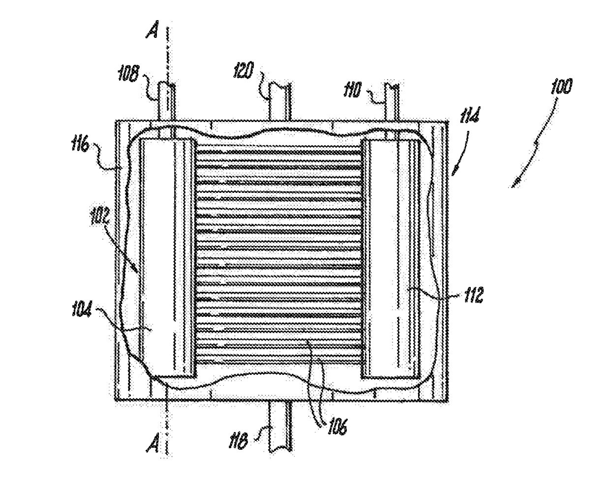
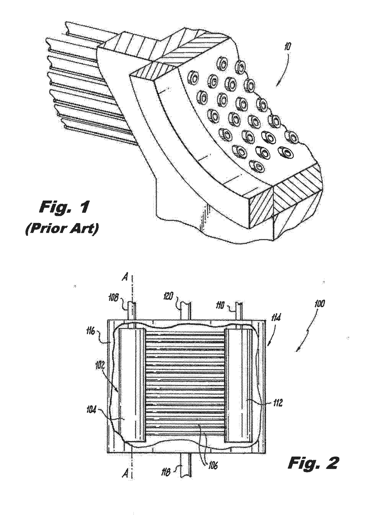
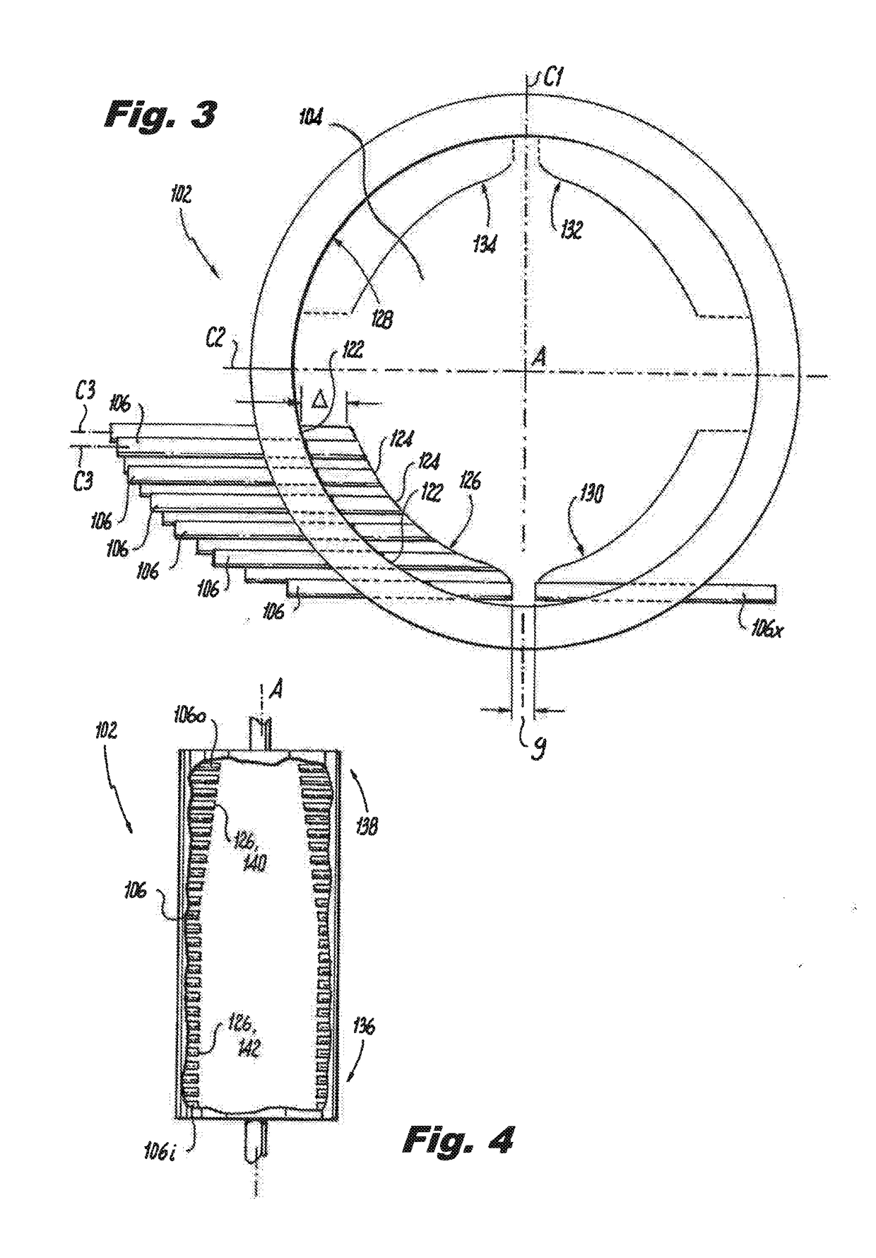
[0023]Reference will now be made to the drawings wherein like reference numerals identify similar structural features or aspects of the subject disclosure. For purposes of explanation and illustration, and not limitation, a partial view of an exemplary embodiment of a heat exchanger in accordance with the disclosure is shown in FIG. 2 and is designated generally by reference character 100. Other embodiments of heat exchangers in accordance with the disclosure, or aspects thereof, are provided in FIGS. 3-4, as will be described. The systems and methods described herein can be used to reduce weight and improve performance, operational life, and manufacturability of heat exchangers, such as in tube and shell configurations.

[0024]A heat exchanger 100 includes a manifold 102 defining a longitudinal axis A, wherein the manifold includes an interior 104 configured for a flow of heat exchange fluid therethrough. A plurality of heat exchanger tubes 106 are connected in fluid communication wi...


PUM


Abstract

A heat exchanger includes a manifold defining a longitudinal axis, wherein the manifold includes an interior configured for a flow of heat exchange fluid therethrough. A plurality of heat exchanger tubes are connected in fluid communication with the interior of the manifold for exchanging heat exchange fluid with the interior of the manifold. Each tube is mounted to the manifold at a tube / manifold interface. Each tube extends into the interior of the manifold from the tube / manifold interface to a respective tube end face that is spaced apart from the from the tube / manifold interface by an offset. The tube end faces collectively define a tube-end profile, e.g., a smooth profile, within the interior of the manifold.

Description

STATEMENT REGARDING FEDERALLY SPONSORED RESEARCH OR DEVELOPMENT[0001]This invention was made with government support under Air Force Research Lab Contract No. FA8650-09-D-2929 DO 0021 awarded by the United States Air Force. The government has certain rights in the invention.BACKGROUND OF THE INVENTION[0002]1. Field of the Invention[0003]The present disclosure relates to heat exchangers, and more particularly to tubes and manifolds such as used in shell and tube heat exchangers.[0004]2. Description of Related Art[0005]Traditional tube shell heat exchangers have been designed with manifolds with cylindrical cross-sections to handle high pressures. An example of such a manifold 10 is shown in FIG. 1. When these heat exchangers are subjected to rapid changes in temperature of the high pressure fluid, there are significant temperature gradients in the assembly with resultant high stresses and strains into the plastic region at the tube / manifold interface that can ultimately result in cra...

Claims


Application Information

Patent Timeline
IPC IPC(8): F28F9/02F28F1/02
CPCF28F9/0282F28F2009/0297F28F1/025F28F9/0243F28F9/182F28D7/16
Inventor SCHWALM, GREGORY K.
Owner HAMILTON SUNDSTRAND CORP
Why Eureka
Try Eureka