
Electronically Controlled Mechanically Adjustable Acoustic Panel System

a technology of electrical control and mechanical adjustment, applied in the field of electrical control mechanical adjustment of acoustic panels, can solve the problems of limiting the user's ability to be precise, complicating the efficacious use of the system by the inexperienced user, and so many adjustments

Inactive Publication Date: 2017-07-13
GRAVES MATTHEW +1
View PDF0 Cites 9 Cited by
  • Summary
  • Abstract
  • Description
  • Claims
  • Application Information

AI Technical Summary

Benefits of technology

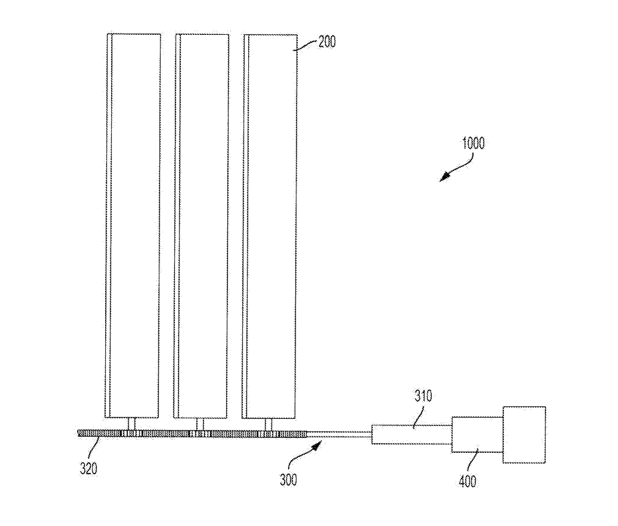
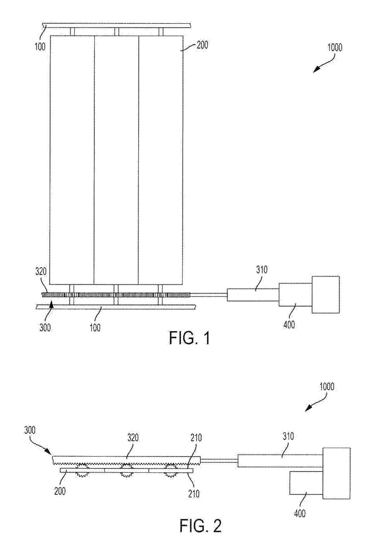
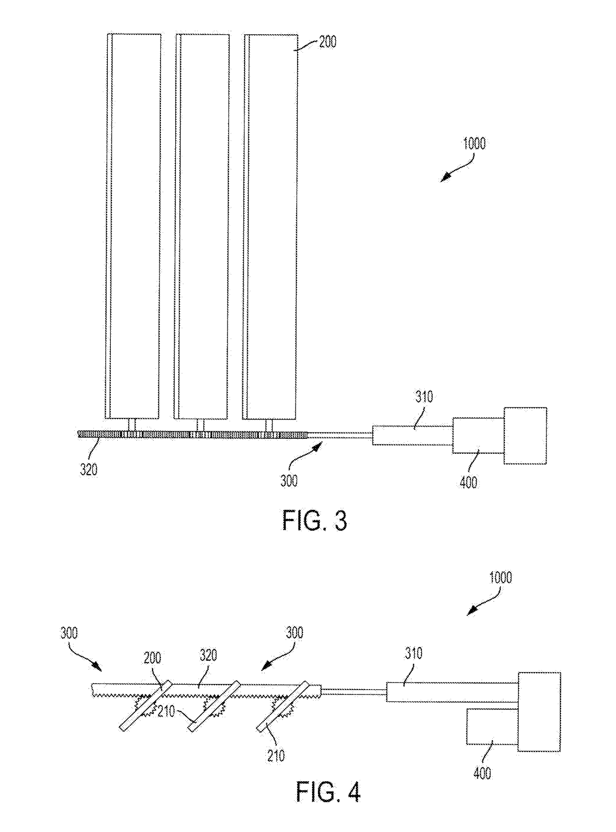
The mechanically adjustable acoustical panel system allows users to optimize the sound of a space for different types of events and performances. The system includes movable, modular panels that can be custom manufactured to fit various surfaces. The panels can be installed throughout a room on any vertical or horizontal surface and may include multiple baffles with different acoustical properties. The present invention provides users with significant ability to optimize the acoustical properties of a given space or venue.

Problems solved by technology

The drawbacks of the graphic equalizer are that it has fixed frequencies and Q, which limits the user's ability to be precise.
A parametric equalizer allows the user to change the frequency and Q. However, this benefit is offset by the fact that this very ability complicates the inexperienced user's efficacious use of the system.
Adjustments can be so complex that needed changes might be difficult to determine.
A parametric equalizer uses knobs for its control functions, which makes it more difficult to visualize the set-up of the equalizer.
Digital audio processing and manipulation is necessarily limited by the physical properties of the venue.
Digital audio processing methods are also limited by the number of speakers surrounding the event and the types of adjustments that may be possible given the equipment provided.
Another limitation of such prior art systems and methods of achieving ideal sound recordings is that the desired amount of digital processing of the sound recorded at a particular venue varies.
Moreover, a large public address system is not always avoidable at a live music concert hall, recording studio or small venue.
Unfortunately, the properties of the room itself cannot be changed without physically removing and replacing existing acoustic panels with a new panels possessing different properties than the original ones.
Thus, none of the prior art systems or methods fully address the need for a single performance space with optimal acoustics for a variety of uses.

Method used


Image

  • Electronically Controlled Mechanically Adjustable Acoustic Panel System
  • Electronically Controlled Mechanically Adjustable Acoustic Panel System
  • Electronically Controlled Mechanically Adjustable Acoustic Panel System

Examples


Embodiment Construction

[0090]The present invention will be discussed hereinafter in detail in terms of various exemplary embodiments according to the present invention with reference to the accompanying drawings. In the following detailed description, numerous specific details are set forth in order to provide a thorough understanding of the present invention. It will be obvious, however, to those skilled in the art that the present invention may be practiced without these specific details. In other instances, well-known structures are not shown in detail in order to avoid unnecessary obscuring of the present invention.

[0091]Thus, all of the implementations described below are exemplary implementations provided to enable persons skilled in the art to make or use the embodiments of the disclosure and are not intended to limit the scope of the disclosure, which is defined by the claims. As used herein, the word “exemplary” or “illustrative” means “serving as an example, instance, or illustration.” Any imple...


PUM


Abstract

An acoustic modulation system for a physical space, said system comprising: at least one acoustic panel, each of said at least one acoustic panel movably attached to a frame; a motor for moving said at least one panel relative to said frame, said motor mechanically connected to each of said at least one panels; a programmable controller, said controller operatively connected to said motor, said controller adapted to selectively engage said motor to move at least one panel of said at least one panel.

Description

BACKGROUND[0001]1. Field of the Invention[0002]The present invention relates to acoustic panels such as diffusers and absorbers and, more particularly, to physical spaces having computer controlled mechanically movable acoustic panels.[0003]2. Description of the Prior Art[0004]It is well know that the acoustic properties of even a well designed physical space are static. Indeed, generally a physical space such as a sound studio is, at best, designed to accommodate a variety of possible sound recordings, including different musical styles and band sizes as well as other types of audio recordings.[0005]Acoustical engineers digitally alter any sound recordings using digital audio processors to provide the best solution to a hypothetical sound profile. This profile is an approximation given the stated use of the venue. As with all approximations or estimates, the results are not unique to each performance that may take place at a venue and may provide suboptimal results based upon the s...

Claims


Application Information

Patent Timeline
IPC IPC(8): E04B1/99G05B19/414G05B19/042G05B19/402E04B1/343E04H3/30
CPCE04B1/994E04B1/343E04H3/30G05B2219/36507G05B19/402G05B19/4145G05B19/0426G05B19/042
Inventor GRAVES, MATTHEWKINNEY, JR., RICHARD
Owner GRAVES MATTHEW
Learn More