
Solar cell module with perovskite layer

a solar cell and perovskite technology, applied in the field of solar cell modules with perovskite layers, can solve the problems of only 1.05v open circuit voltage of solar cells in these prior arts, serious damage to the environment, and affect the living organisms in the biosphere, so as to prevent the decomposition of the perovskite layer, reduce the effect of photovoltaic conversion efficiency and avoid further instability

Inactive Publication Date: 2017-07-06
CPC CORPORATION
View PDF9 Cites 14 Cited by
  • Summary
  • Abstract
  • Description
  • Claims
  • Application Information

AI Technical Summary

Benefits of technology

This patent describes a solar cell module that uses a perovskite layer. The module is made up of multiple solar cell units that are protected by an insulation layer and connected in series by conductors. This design results in better open circuit voltage and stability compared to conventional solar cells that are connected in series by labor. The insulation layer also prevents decomposition of the perovskite layer caused by contact with water in the atmosphere. Overall, this improves the industrial applicability of perovskite solar cells.

Problems solved by technology

The use of large amount of non-renewable resource by human being cause serious damage to the environment and also affects living organisms in the biosphere.
However, the open circuit voltage of the solar cell in these prior arts is only 1.05V.
Moreover, connection of solar cells available now in series requires other techniques or machines.
The above method not only increases impedance, the products produced by the method also have defects easily.
The perovskite solar cell has shortcomings of low stability, low safety and low photoelectric conversion efficiency.

Method used


Image

  • Solar cell module with perovskite layer
  • Solar cell module with perovskite layer
  • Solar cell module with perovskite layer

Examples


Embodiment Construction

[0022]In order to learn functions and features of the present invention, please refer to the following embodiments with figures and detailed descriptions.

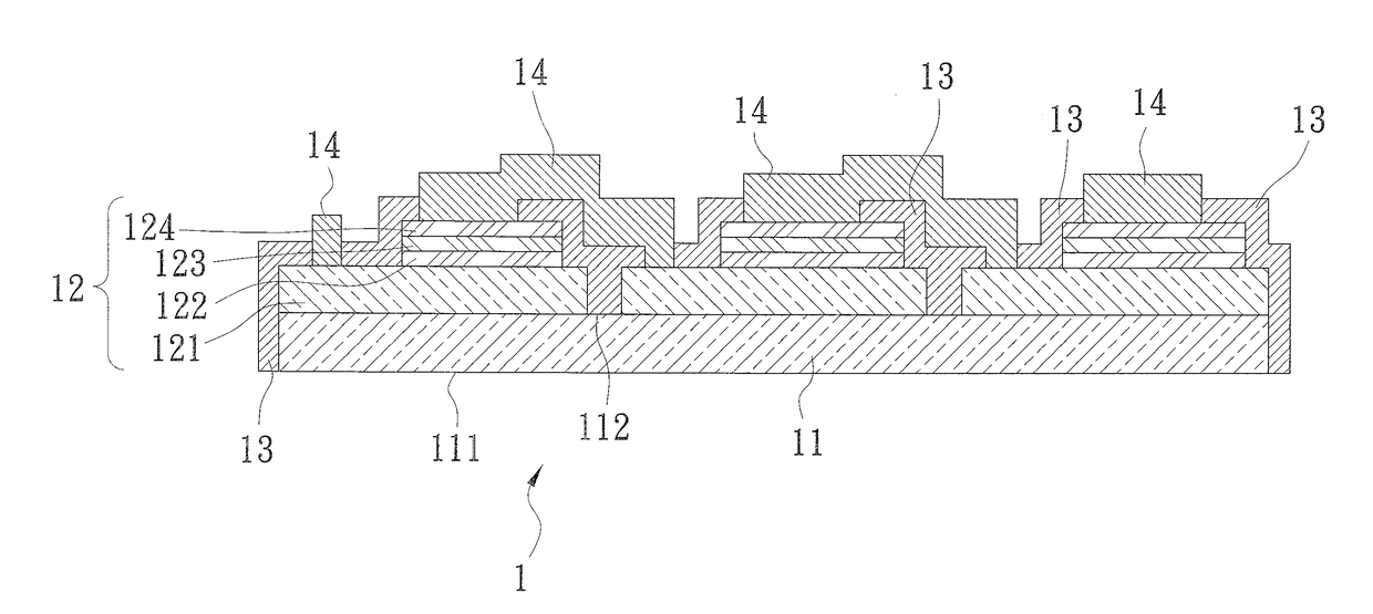
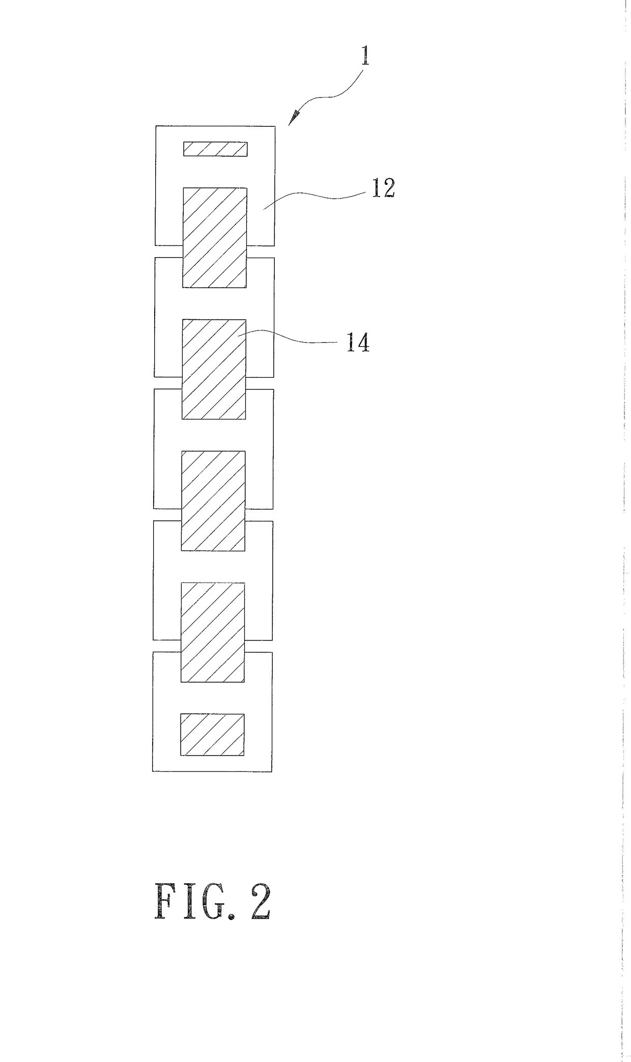
[0023]Refer to FIG. 1, a solar cell module with a perovskite layer 1 of the present invention includes a transparent substrate 11, a plurality of solar cell units 12, an insulation layer 13, and a plurality of conductors 14.

[0024]The transparent substrate 11 includes a light incident surface 111 and a surface 112 opposite to the light incident surface 111. The transparent substrate 11 can be either a rigid substrate or a flexible substrate made from one of the following materials: glass, sapphire, polyethylene terephthalate (PET), and polyethylene naphthalate (PEN).

[0025]The solar cell units 12 are arranged at the surface 112 of the transparent substrate 11. Each solar cell unit 12 consists of a transparent conductive layer 121, a first carrier transport layer 122, a perovskite layer 123 and a second carrier transport layer 124. Th...


PUM


Abstract

A solar cell module with a perovskite layer is revealed. The solar cell module includes a transparent substrate with a light incident surface and a surface opposite to the light incident surface. A plurality of solar cell units is disposed on the surface and each solar cell includes a transparent conductive layer, a first carrier transport layer, a perovskite layer and a second carrier transport layer. An insulation layer is not only located between the adjacent solar cell units but also covered over the solar cell units. A plurality of conductors is used for electrical connection of the plurality of solar cell units in series. Thus the solar cell module has better open circuit voltage and higher stability owing to connection way of the solar cell units in series and the insulation layer.

Description

BACKGROUND OF THE INVENTION[0001]Field of the Invention[0002]The present invention relates to a solar cell module with a perovskite layer, especially to a solar cell module formed by a plurality of perovskite solar cell units and the solar cell units are electrically connected in series at once by a plurality of conductors. Thereby the solar cell module has better open circuit voltage and higher stability.[0003]Description of Related Art[0004]The use of large amount of non-renewable resource by human being cause serious damage to the environment and also affects living organisms in the biosphere. In recent years, various countries now develop and introduce renewable energy resources owing to environmental consciousness. Among these renewable energy resources, solar energy has become one of the development priorities of renewable energy technology due to unlimited source of energy and low pollution.[0005]Among a series of new generation solar cells, perovskite solar cells with perovs...

Claims


Application Information

Patent Timeline
Patent Type & Authority Applications(United States)
IPC IPC(8): H01G9/20H01L51/00H01L25/04H01L51/44H01L51/42H10K99/00
CPCH01G9/2013H01L51/448H01L51/445H01L51/0077H01L25/047H01L51/0096H01L51/424Y02E10/549Y02E10/542H10K85/50H10K39/12Y02E10/50H10K30/20H10K30/83H10K30/88H10K39/10H10K77/10H10K85/30H10K39/601
Inventor HUANG, KUAN-CHIEHLAI, LI-CHUNG
Owner CPC CORPORATION
Learn More