
Flexible substrate and manufacturing method thereof and display device

Active Publication Date: 2017-07-06
BOE TECH GRP CO LTD +1
View PDF0 Cites 4 Cited by
  • Summary
  • Abstract
  • Description
  • Claims
  • Application Information

AI Technical Summary

Benefits of technology

The present invention provides a flexible substrate and a manufacturing method thereof, and a display device. The flexible substrate can be easily stripped off after it is manufactured, and the yield rate is improved. The invention uses a mesh connection structure that lowers the cohesion force between layers, reducing stripping difficulty. The method does not use UV light or chemical liquid and avoids the risk of damaging the flexible substrate, increasing the yield rate. Compared with the roll-to-roll process in a flexible production line, the method saves costs and has process compatibility with ordinary production lines.

Problems solved by technology

The process of directly adhering the flexible substrate on the glass substrate has many problems.
For example, the UV decomposition method will cause irreversible damage to the liquid crystals, and is not suitable for the One Drop Fill (ODF) process, so the problem of liquid crystal dripping in vacuum needs to be solved again.
The heat-softening method needs to consider the material of the flexible substrate and the temperature of the technical process, and the effect is not ideal.
In addition, the process of directly adhering the flexible substrate on the glass substrate also has the defects of insufficient adhesion strength, being unable to produce large-scaled substrates, easily damaging the flexible substrate during the stripping off process, etc.

Method used


Image

  • Flexible substrate and manufacturing method thereof and display device
  • Flexible substrate and manufacturing method thereof and display device
  • Flexible substrate and manufacturing method thereof and display device

Examples


Embodiment Construction

[0047]In the following will be described the technical solutions of embodiments of the present invention in detail in conjunction with the accompanying drawings. Obviously, the described embodiments are merely for illustrating and explaining the present invention, and are not intended to limit the present invention.

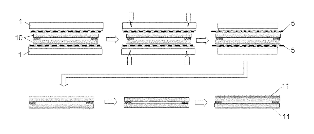
[0048]The present invention provides a manufacturing method of a flexible substrate. As shown in FIG. 1, the manufacturing method comprises the following steps:

[0049]S1: disposing a detachable layer on a rigid substrate, and fixing a flexible base on the rigid substrate by the detachable layer, wherein the detachable layer comprises a mesh layer and a plurality of mutually independent supporting parts disposed in meshes of the mesh layer;

[0050]S2: forming a functional layer on the flexible base to obtain a flexible substrate;

[0051]S3: separating the flexible substrate from the rigid substrate by applying an external force applied on the mesh layer.

[0052]It should be noted...


PUM


Abstract

The present invention discloses a flexible substrate and a manufacturing method thereof, and a display device, comprising: disposing a detachable layer on a rigid substrate, and fixing the flexible base on the rigid substrate by the detachable layer, wherein the detachable layer comprises a mesh layer and a plurality of mutually independent supporting parts disposed in meshes of the mesh layer; forming a functional layer on the flexible base to obtain a flexible substrate; separating the flexible substrate from the rigid substrate by applying an external force on the mesh layer. The present invention makes it easier for the flexible substrate to be stripped off after it is manufactured, improves the yield rate; moreover, the present invention has the process compatibility of ordinary production lines, and saves costs.

Description

TECHNICAL FIELD[0001]Embodiments of the present invention relate to a flexible substrate and a manufacturing method thereof, and a display device including the flexible substrate.BACKGROUND OF THE INVENTION[0002]With the rapid development of display technologies, display products are becoming more and more diversified and humanized, and flexible displays represent an important development direction.[0003]The currently existing manufacturing method of a flexible substrate based on a glass substrate directly adheres a flexible substrate on a glass substrate, and when it needs to be stripped off, the adhesive glue is degenerated by an UV decomposition method or a heat softening method, so that it is stripped off. The process of directly adhering the flexible substrate on the glass substrate has many problems. For example, the UV decomposition method will cause irreversible damage to the liquid crystals, and is not suitable for the One Drop Fill (ODF) process, so the problem of liquid c...

Claims


Application Information

Patent Timeline
IPC IPC(8): G02F1/1333
CPCG02F1/133305G02F2001/133354G02F1/13338G02F1/133351G02F1/133302G02F1/133354
Inventor WANG, JUNWEI
Owner BOE TECH GRP CO LTD
Learn More