
Device and method for producing a dynamic reference signal for a driver circuit for a semiconductor power switch

a driver circuit and power switch technology, applied in the direction of electronic switching, pulse technique, electrical apparatus, etc., can solve the problems of high thermal load damage, and thermal destruction of the power semiconductor switch,

Active Publication Date: 2017-06-29
POWER INTEGRATIONS INC
View PDF1 Cites 9 Cited by
  • Summary
  • Abstract
  • Description
  • Claims
  • Application Information

AI Technical Summary

Benefits of technology

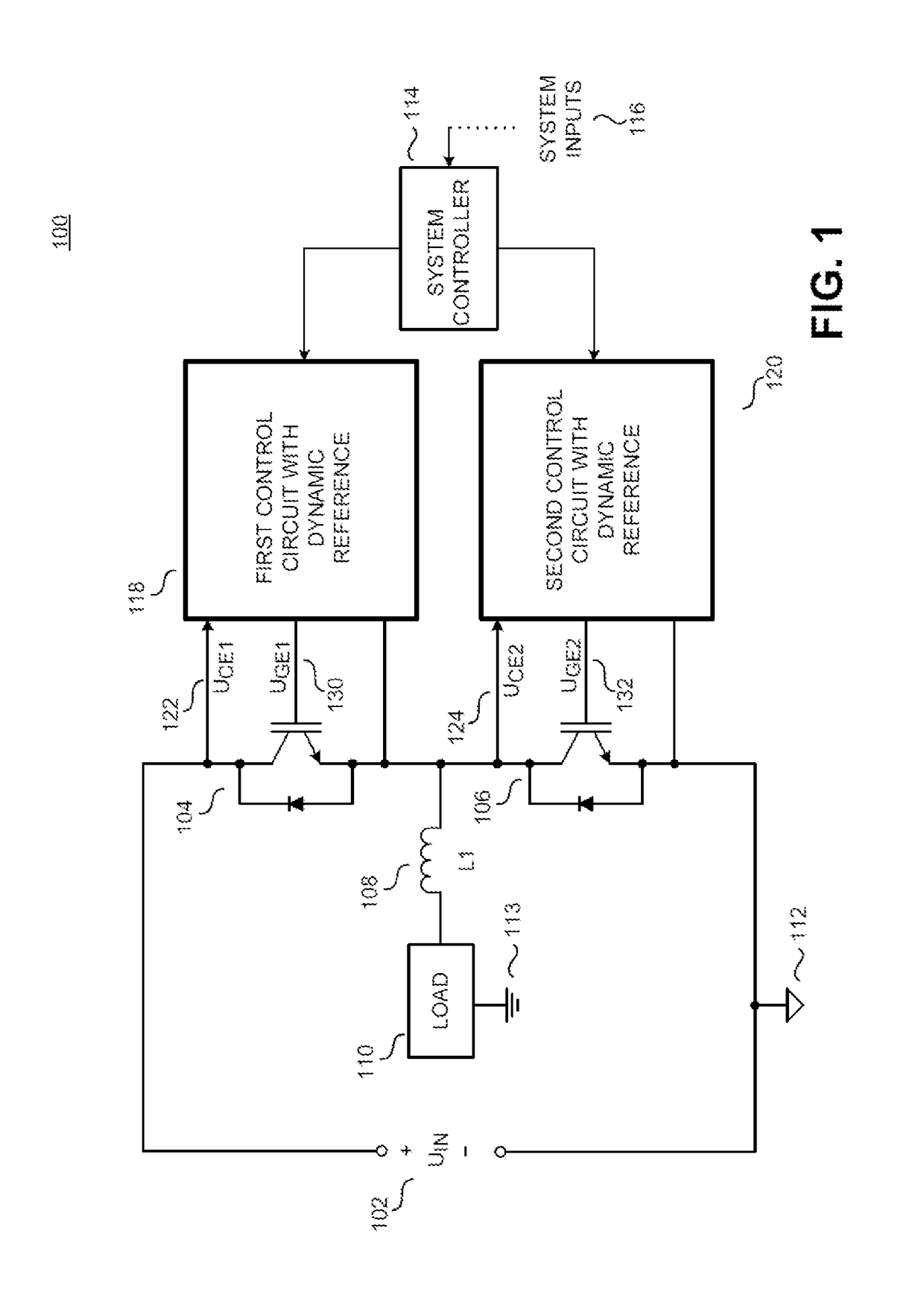
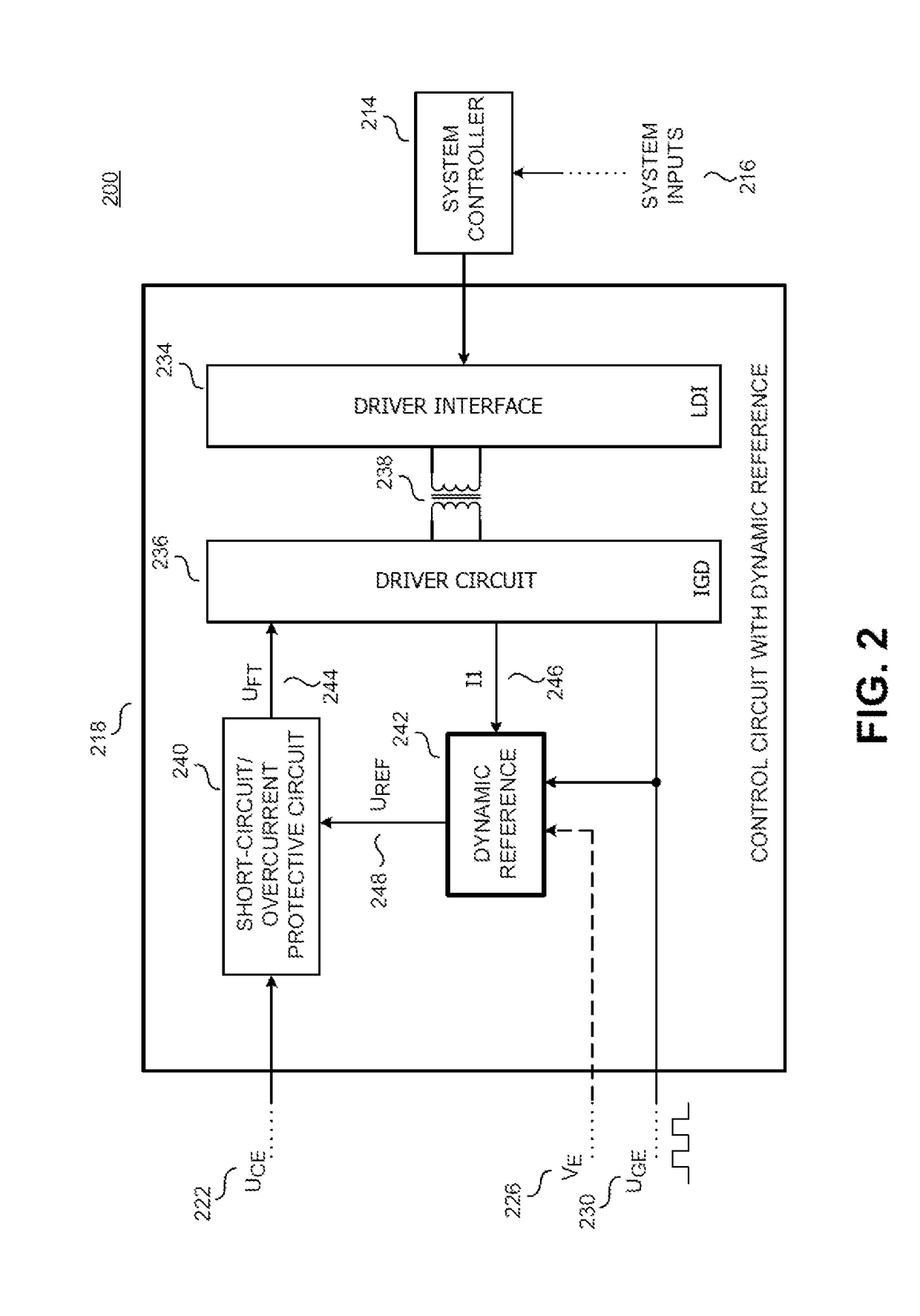
The invention is a device that can reliably and quickly detect short-circuit and overcurrent states in a power semiconductor switch. It achieves this by momentarily increasing the level of the reference signal in response to a switchover of the control signal. This device is cost-effective and robust, with minimal temperature drift and requires minimal outlay.

Problems solved by technology

Short circuits or excessively increased currents can therefore rapidly lead to the thermal destruction of the power semiconductor switches.
This results in a high thermal loading of the power semiconductor switch, which can incur damage after a relatively short time.

Method used


Image

  • Device and method for producing a dynamic reference signal for a driver circuit for a semiconductor power switch
  • Device and method for producing a dynamic reference signal for a driver circuit for a semiconductor power switch
  • Device and method for producing a dynamic reference signal for a driver circuit for a semiconductor power switch

Examples


Embodiment Construction

[0057]The following description presents numerous details to enable a profound understanding of the present invention. It is clear to the person skilled in the art, however, that the specific details are not necessary to implement the present invention. Elsewhere, known devices and methods are not portrayed in detail, in order that understanding the present invention is not made more difficult unnecessarily.

[0058]In the present description, a reference to “an embodiment”, “a configuration”, “an example” or “example” means that a specific feature, a structure or property that is described in association with this embodiment is included in at least one embodiment of the present invention. In this regard, the phrases “in one embodiment”, “an example” or “example” at various points in this description do not necessarily all refer to the same embodiment or the same example. Furthermore, the specific features, structures or properties can be combined in arbitrary suitable combinations and...


PUM


Abstract

A device (442) for producing a dynamic reference signal (UREF) for a control circuit for a power semiconductor switch comprises a reference signal generator (442) for providing a dynamic reference signal (UREF), which has a stationary signal level after elapse of a predefined time following a switching process of the power semiconductor switch, a passive charging circuit (450) which is configured to increase a signal level of the dynamic reference signal in reaction to a switching of a control signal of the power semiconductor switch from an OFF state to ON state for at least one part of the predefined time above the stationary signal level, in order to produce the dynamic reference signal and an output (A) for tapping the dynamic reference signal (UREF).

Description

TECHNICAL FIELD[0001]The present invention relates to a device and a method for producing a variable reference signal for a driver circuit for a semiconductor power switch. Such devices are used for example for detecting a short-circuit or overcurrent state in an IGBT (“Insulated Gate Bipolar Transistor”).BACKGROUND[0002]In some power semiconductor switches, high voltages can be applied and high currents can be carried. Short circuits or excessively increased currents can therefore rapidly lead to the thermal destruction of the power semiconductor switches. Therefore, power semiconductor switches can have protective circuits for detecting a short-circuit or overcurrent state. One possibility for detecting these states is the indirect monitoring of the current through the power semiconductor switch on the basis of a voltage dropped across the power semiconductor switch. After the power semiconductor switch has been switched on, said voltage should fall quickly from a relatively high ...

Claims


Application Information

Patent Timeline
Patent Type & Authority Applications(United States)
IPC IPC(8): H03K17/082H03K5/08
CPCH03K5/08H03K17/0828H03K17/082H03K17/168H03K17/163
Inventor RATZ, MARKUS
Owner POWER INTEGRATIONS INC
Learn More