
System and Method for Controlling a Fundus Imaging Apparatus

a technology of ophthalmic apparatus and control system, which is applied in the field of ophthalmic apparatus, a system and a control method of ophthalmic apparatus, can solve the problems of limited light that can be used to measure the fundus, limited eye safety concerns, and difficulty for a slo to detect reflective light, so as to reduce the amount of light and increase the quality of the image

Active Publication Date: 2017-06-29
CANON KK
View PDF4 Cites 20 Cited by
  • Summary
  • Abstract
  • Description
  • Claims
  • Application Information

AI Technical Summary

Benefits of technology

The patent text describes a method for improving the image quality of fundus images obtained using an ophthalmoscope. This is achieved by shifting the center position of the illumination beam away from the center of the pupil during scanning. This results in additional light incident on the fundus and improves the quality of the image obtained.

Problems solved by technology

One of the challenges for gathering information about the fundus is that the reflectance at the retina (a part of the fundus) is very small (around 0.1%).
Also, the amount of light that can be used to measure the fundus is limited by eye safety concerns.
Thus, it can be difficult for a SLO to detect reflective light.
The inventors have determined that in some cases, where the prior art method of co-centering the center of the illumination beam with the center of the subject's pupil actually makes it harder to get a good fundus image.

Method used


Image

  • System and Method for Controlling a Fundus Imaging Apparatus
  • System and Method for Controlling a Fundus Imaging Apparatus
  • System and Method for Controlling a Fundus Imaging Apparatus

Examples


first embodiment

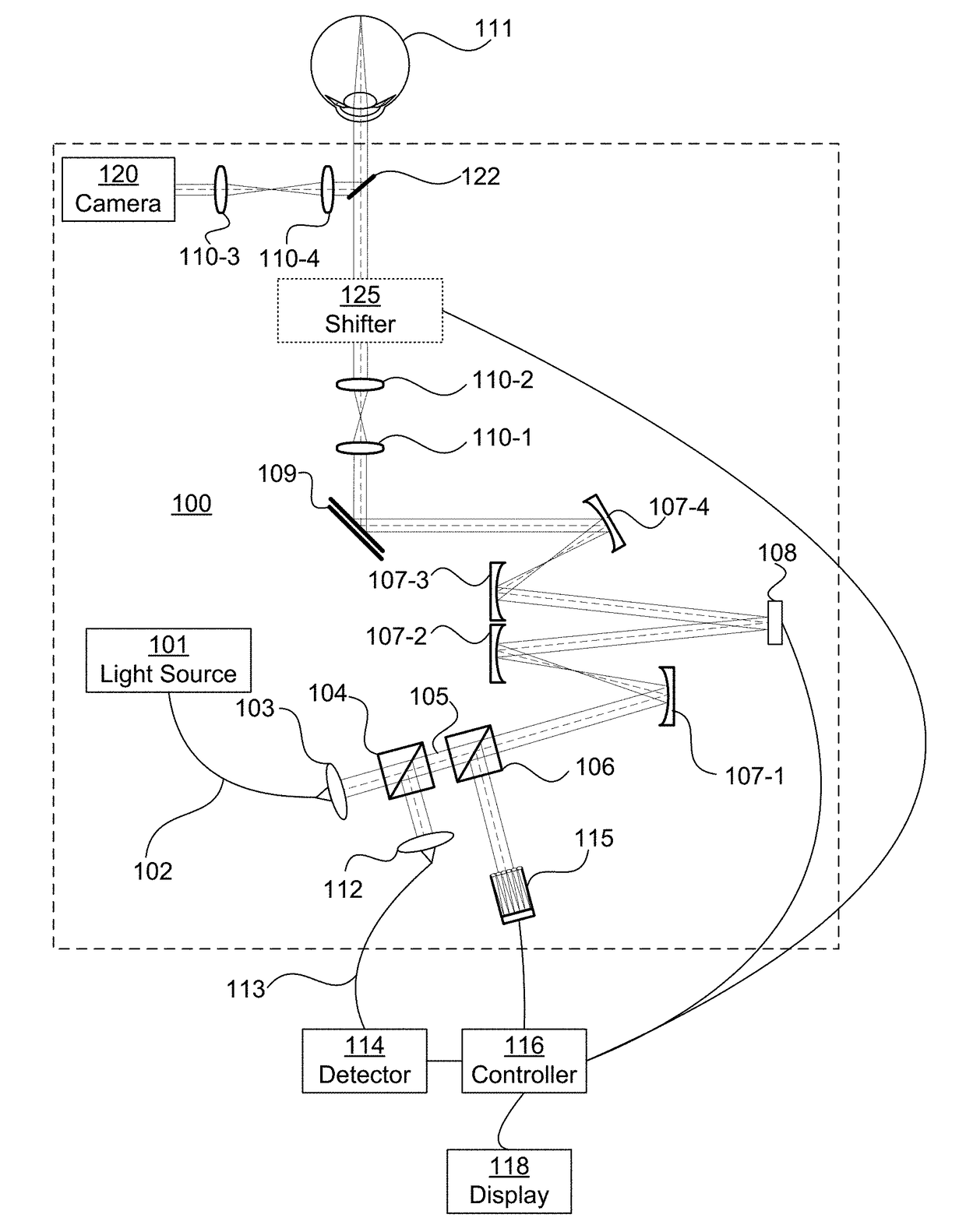
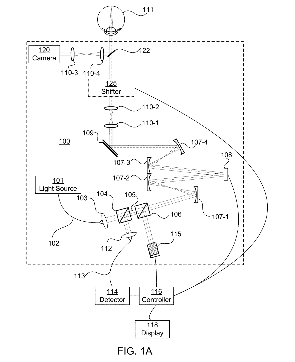
[0042]A first embodiment is described with reference to an ophthalmoscope 100 such as fundus image photographing apparatus illustrated in FIG. 1A. Embodiments are directed towards systems, methods, non-transitory computer readable medium, and software which are used in connection with an imaging system such as an ophthalmoscope 100. FIG. 1A is an illustration of an exemplary ophthalmoscope 100. An ophthalmoscope 100 is a system or apparatus for obtaining information about an interior portion of the eye 111 (e.g., the fundus or retina).

[0043]An exemplary embodiment may be a scanning ophthalmoscope. A scanning ophthalmoscope scans a spot across the eye 111 with a scanner 109. The spot may be a spot of light from a light source 101 that is scanned across the eye 111.

exemplary embodiment 100

[0044]In an exemplary embodiment 100, the spot of light is produced by a light source 101. The light source 101 may be incorporated into the ophthalmoscope 100; alternatively, the ophthalmoscope 100 may include an input for receiving the light source 101. The input for the light source 101 may be a fiber optic input 102 or a free space input (not shown). The light source 101 may be a laser, a broadband light source, or multiple light sources. In an exemplary embodiment, the light source 101 is a super luminescent diode (SLD) light source having a wavelength of 840 nm. The wavelength of the light source 101 is not particularly limited, but the wavelength of the light source 101 for fundus image photographing is suitably set in a range of approximately 800 nm to 1,500 nm in order to reduce glare perceived by a person being inspected and to maintain imaging resolution.

[0045]In an exemplary embodiment, light emitted from the light source 101 passes through a single-mode optical fiber 10...


PUM


Abstract

A system, method, medium, controller, or ophthalmoscope for imaging a fundus of a subject. Estimating a first illumination center position for an illumination beam relative to a center position of a pupil of the subject. The first illumination center position may be offset from the center position of the pupil. Sending instructions to an ophthalmoscope to shift a center position of the illumination beam to the first illumination center position.

Description

CROSS-REFERENCE TO RELATED APPLICATIONS[0001]This application claims the benefit of U.S. Provisional Application No. 62 / 271,608, filed Dec. 28, 2015. U.S. Provisional Application No. 62 / 271,608 is hereby incorporated by reference in its entirety.BACKGROUND[0002]Field of Art[0003]The present disclosure relates to an ophthalmic apparatus, a system and a method for controlling an ophthalmic apparatus.[0004]Description of the Related Art[0005]An ophthalmoscope is an apparatus for gathering information about the interior portion of an eye (fundus). A simple direct view ophthalmoscope is a handheld device used by an optician to directly view the fundus which may include light source, aperture, and one or more lenses. An electronic ophthalmoscope use one or more sensors to obtain fundus images. These fundus images are then displayed to the optician with a display device. A high resolution ophthalmoscope may use lasers to obtain high resolution fundus images. A high resolution ophthalmoscop...

Claims


Application Information

Patent Timeline
IPC IPC(8): A61B3/12G02B27/00A61B3/14A61B3/00A61B3/10
CPCA61B3/1225A61B3/0041A61B3/0025A61B3/1025A61B3/14G02B27/0068A61B3/102G02B26/06A61B3/12
Inventor KAWAKAMI, TOMOAKINOZATO, KOJIUTSUNOMIYA, NORIHIKO
Owner CANON KK
Learn More