Tapered Roller Bearing

Inactive Publication Date: 2017-06-22
JTEKT CORP
View PDF13 Cites 0 Cited by
  • Summary
  • Abstract
  • Description
  • Claims
  • Application Information

AI Technical Summary

Benefits of technology

The invention aims to reduce friction between the cage and lubricant holding member in a tapered roller bearing, which can lead to a smaller size of the bearing.

Problems solved by technology

Thus, when the cage and the lubricant holding member are in contact with each other, friction may occur between the cage and the lubricant holding member to affect a rotating operation of the bearing.
In general, the cage is formed of metal and manufactured by press molding, and thus, changing the shape of the cage is difficult.

Method used


Image

  • Tapered Roller Bearing
  • Tapered Roller Bearing
  • Tapered Roller Bearing

Examples


Embodiment Construction

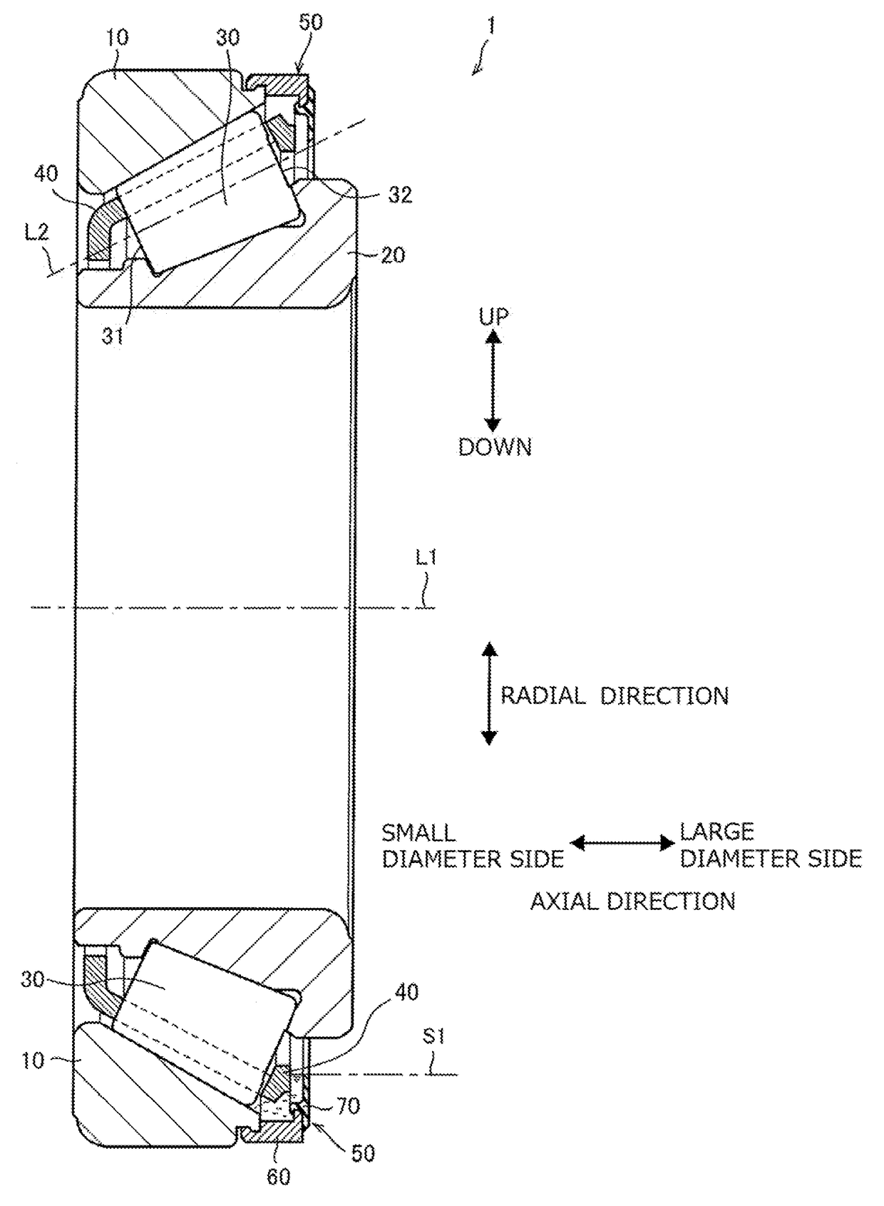
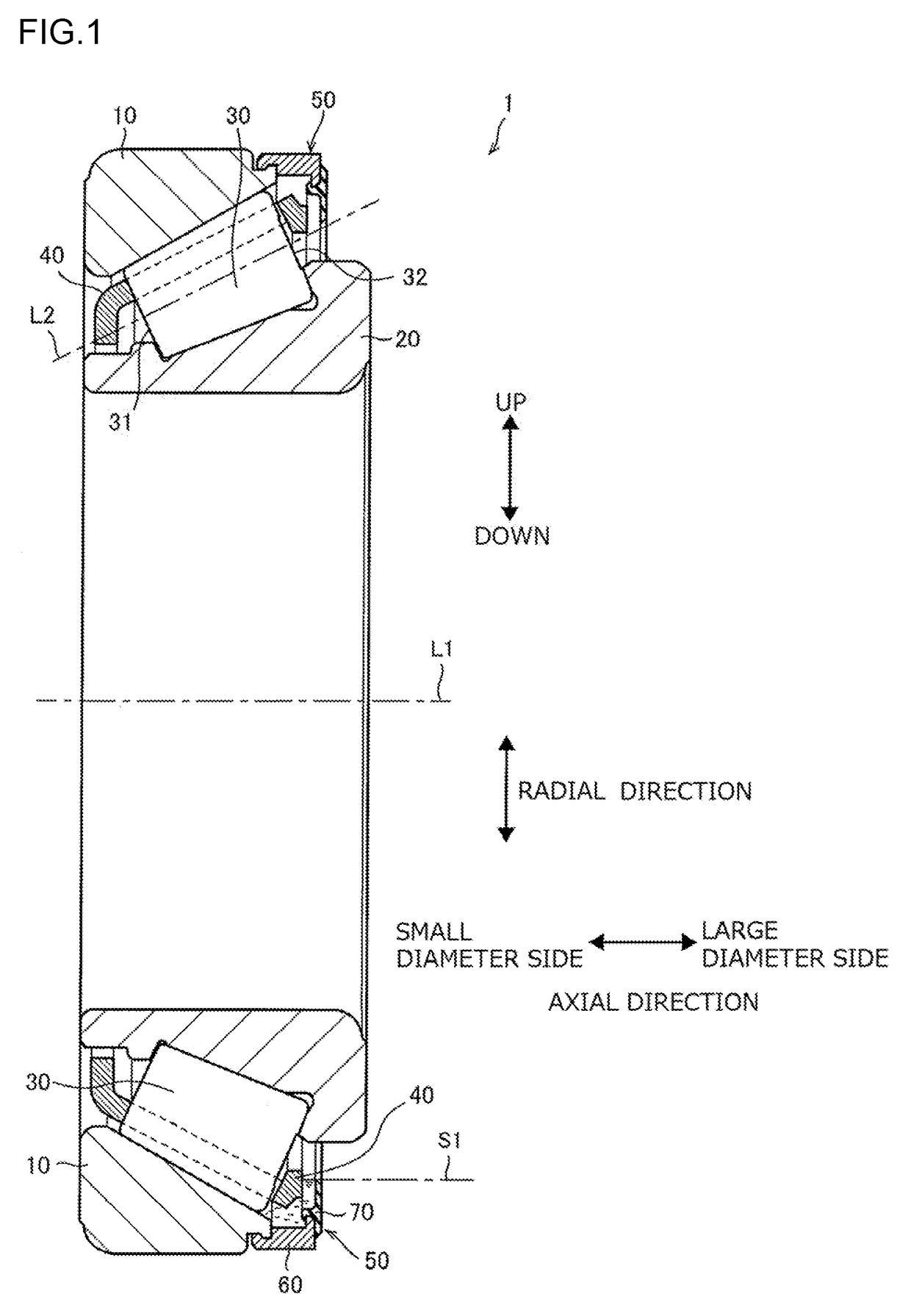
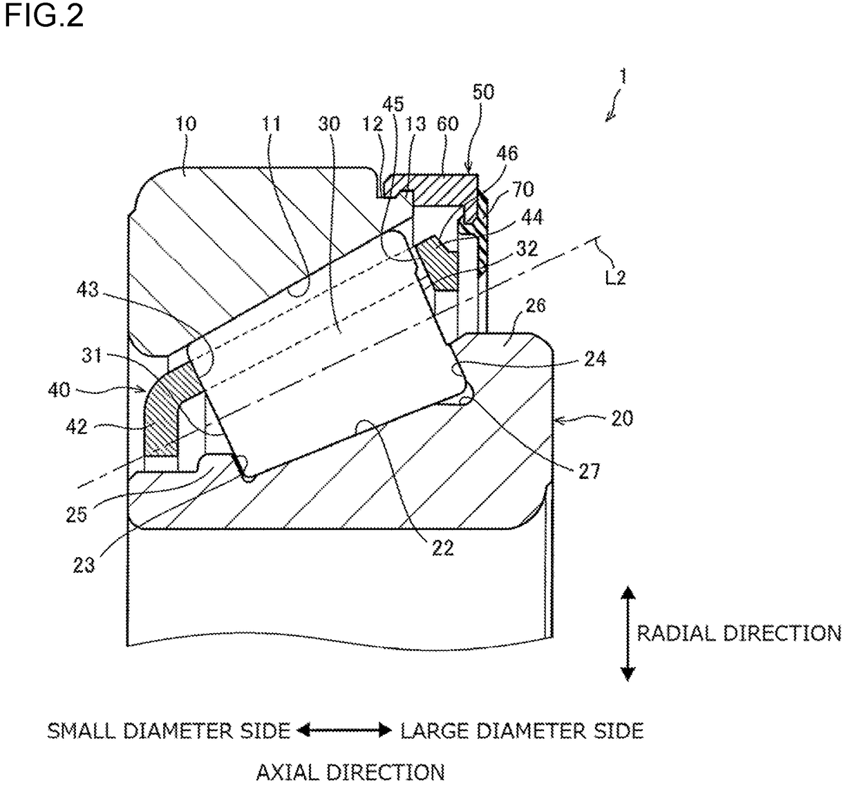
[0018]A tapered roller bearing in the invention includes an outer ring, an inner ring, a plurality of tapered rollers, a resin cage, and a lubricant holding member. The outer ring has a first raceway surface on its inner peripheral surface. The inner ring has a second raceway surface on its outer peripheral surface and is arranged coaxially with the outer ring. The tapered rollers are arranged in a space between the first raceway surface and the second raceway surface. Each of the tapered rollers is inclined with respect to a bearing axis such that a distance between a roller axis and a bearing axis increases from a small-diameter-side bottom face toward a large-diameter-side bottom face. A plurality of pockets is formed in the cage so that the tapered rollers are housed in the pockets. The lubricant holding member is fixed integrally to the outer ring. The lubricant holding member includes a circular-ring-like annular portion and a cylindrical tubular portion. The tubular portion h...


PUM


Abstract

A tapered roller bearing includes an outer ring, an inner ring, tapered rollers, a cage, and a lubricant holding member. The cage is formed of resin. Since the cage is formed of resin, the tapered roller bearing can be downsized with contact between the cage and the lubricant holding member avoided.

Description

INCORPORATION BY REFERENCE[0001]The disclosure of Japanese Patent Application No. 2015-245959 filed on Dec. 17, 2015 including the specification, drawings and abstract, is incorporated herein by reference in its entirety.BACKGROUND OF THE INVENTION1. Field of the Invention[0002]The invention relates to a tapered roller bearing, and in particular, to a tapered roller bearing that stores a lubricant in a space where tapered rollers roll.2. Description of the Related Art[0003]A tapered roller bearing includes an outer ring, an inner ring, a plurality of tapered rollers, and a cage. The tapered rollers are arranged such that an axis of each roller around which the roller rolls is inclined with respect to an axis of the tapered roller bearing. A large-diameter bottom face (hereinafter also referred to as a roller large end face) of the tapered roller is arranged outward of a small-diameter bottom face (hereinafter also referred to as a roller small end face) in a radial direction of the ...

Claims


Application Information

Patent Timeline
IPC IPC(8): F16C33/78F16C33/46F16C19/36
CPCF16C33/7813F16C2240/46F16C33/4635F16C19/364F16C33/46F16C33/56F16C33/583F16C33/664F16C2240/40F16C33/6651F16C2361/61
Inventor SUZUKI, AKIYUKI
Owner JTEKT CORP
Why Eureka
Try Eureka