
Frame assembly for a front mounted primary bus connector and method of construction

a primary bus connector and chassis cabinet technology, applied in the direction of switches with withdrawable carriages, contacts, protective switch details, etc., can solve the problems of high electromotive force, increased temperature, and connection may need periodic maintenan

Active Publication Date: 2017-06-15
SCHNEIDER ELECTRIC USA INC
View PDF13 Cites 8 Cited by
  • Summary
  • Abstract
  • Description
  • Claims
  • Application Information

AI Technical Summary

Benefits of technology

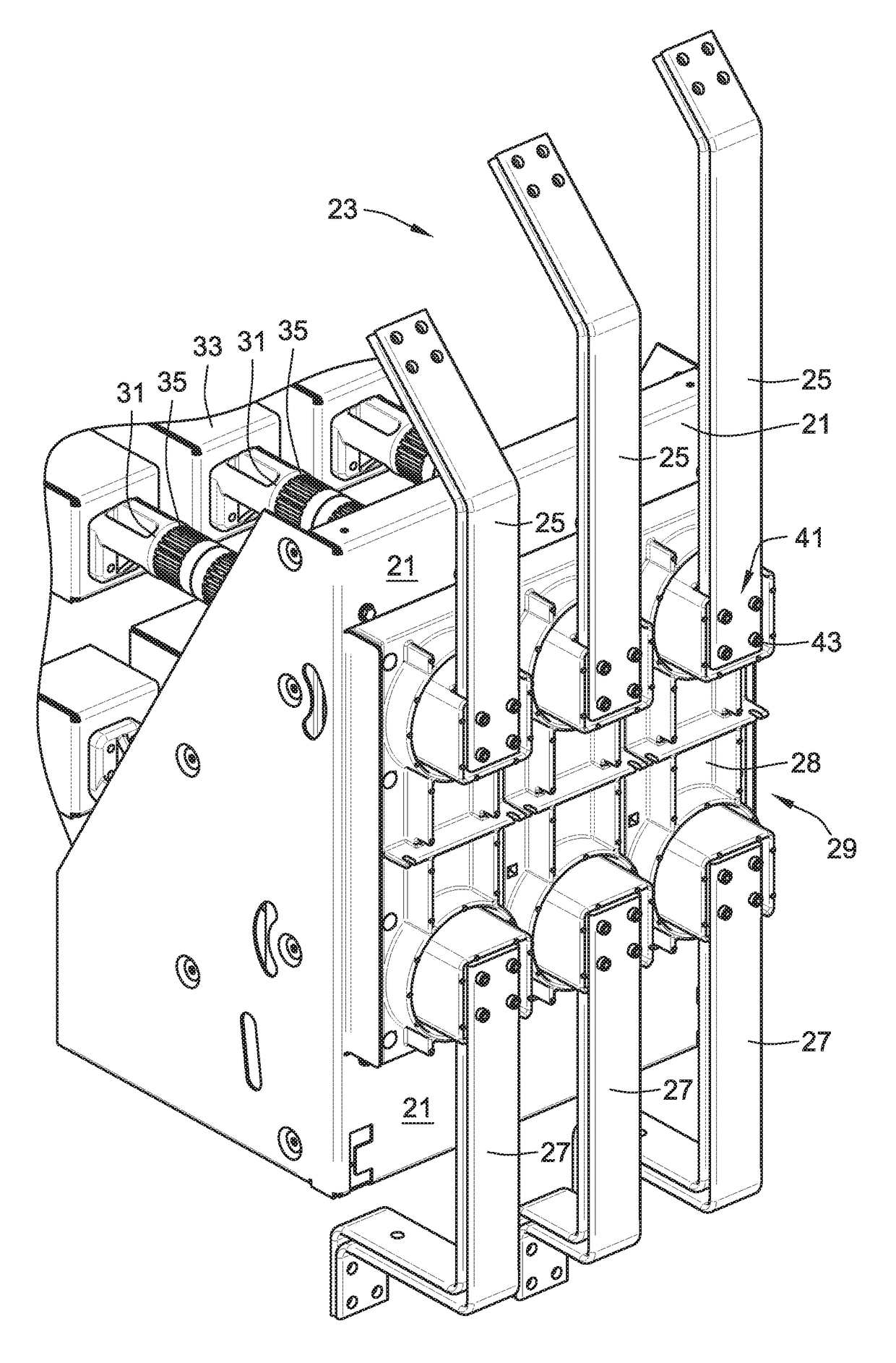
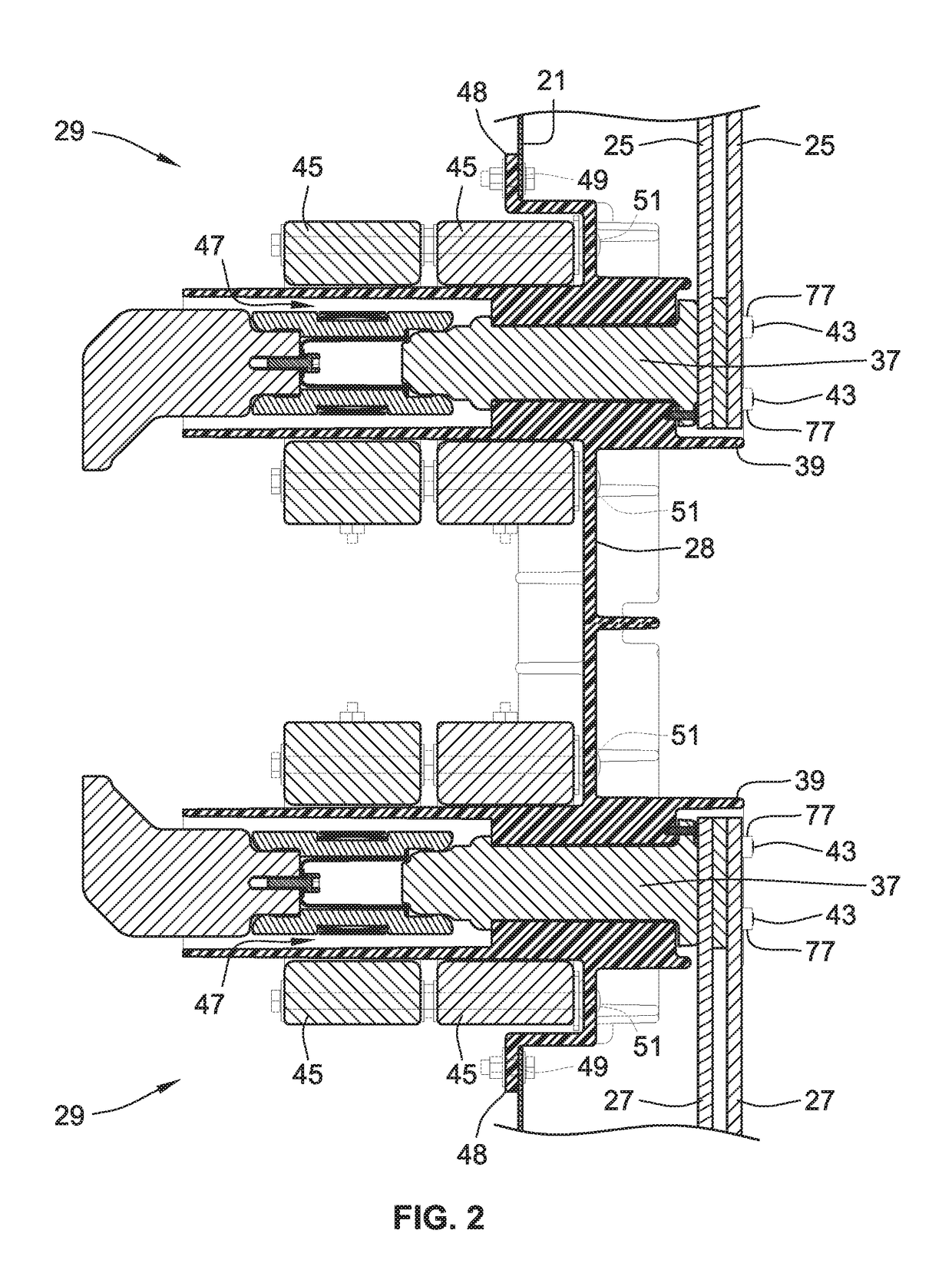
The present invention is a current transformer bushing and primary bus connector assembly that allows for front access to mounting hardware for the riser and feeder bus. This means that hardware can be mounted and torqued from the front of the switchgear while the bushing is in place. This design provides easier construction and maintenance of switchgear.

Problems solved by technology

Large voltages generate high electromotive forces and heat which can loosen the bolted connections in a draw out circuit breaker section of a Switchgear Cabinet.
Thus, the bolted connections may need to undergo periodic maintenance to properly torque the bolted connections.
Proper torque is required on bus connections to prevent an increase in resistance which in turn creates an increase in temperature and can lead to thermal runaway.
With increased demands for smaller footprint and utilization of less space, as generally discussed in U.S. Pat. No. 7,4540,368 to Parker et al., the switchgear cabinets may need to be placed where access to the rear portion of the breaker section from the back panels of the switchgear cabinet is difficult.

Method used


Image

  • Frame assembly for a front mounted primary bus connector and method of construction
  • Frame assembly for a front mounted primary bus connector and method of construction
  • Frame assembly for a front mounted primary bus connector and method of construction

Examples


Embodiment Construction

[0015]As an initial matter, it will be appreciated that the development of an actual, real commercial application incorporating aspects of the disclosed embodiments will require many implementation specific decisions to achieve the developer's ultimate goal for the commercial embodiment. Such implementation specific decisions may include, and likely are not limited to, compliance with system related, business related, government related and other constraints, which may vary by specific implementation, location and from time to time. While a developer's efforts might be complex and time consuming in an absolute sense, such efforts would nevertheless be a routine undertaking for those of skill in this art having the benefit of this disclosure.

[0016]It should also be understood that the embodiments disclosed and taught herein are susceptible to numerous and various modifications and alternative forms. Thus, the use of a singular term, such as, but not limited to, “a” and the like, is n...


PUM


Abstract

A front-accessible bus-connection mounting frame assembly in a draw out switchgear cabinet is fastened to the back wall of the breaker cabinet. The frame assembly provides for insertion and bayonet mounting of a primary bus connector's cylindrical conductor onto the mounting frame. The primary bus connector is bayonet mounted on the internal ribs of a central cylinder of the mounting frame assembly. The primary bus connector is then fixed in position by bolts front mounted down the central cylinder and out through a bus riser fitted at the back of the mounting frame assembly to establish electrical continuity. The central cylinder further provides a current transformer bushing tube around the primary bus connector and necessary flanges to mount the mounting frame assembly to the back wall and secure the current transformers around the bushing.

Description

FIELD OF THE INVENTION[0001]The present invention relates to apparatus and methods for constructing a bus conductor-to-primary bus connector for a draw out circuit breaker chassis cabinet which is able to be tightened from the front side of a switchgear cabinet.BACKGROUND OF THE INVENTION[0002]Large voltages generate high electromotive forces and heat which can loosen the bolted connections in a draw out circuit breaker section of a Switchgear Cabinet. Thus, the bolted connections may need to undergo periodic maintenance to properly torque the bolted connections. Re-torque of fasteners may be required if a thermal imaging, constant thermal monitoring, or performance issues indicate that a joint has loosened. Proper torque is required on bus connections to prevent an increase in resistance which in turn creates an increase in temperature and can lead to thermal runaway.[0003]With increased demands for smaller footprint and utilization of less space, as generally discussed in U.S. Pat...

Claims


Application Information

Patent Timeline
Patent Type & Authority Applications(United States)
IPC IPC(8): H02B1/21H01H71/02H01H69/00H02B11/173
CPCH02B1/21H01H69/00H01H71/0207H02B11/173H02B11/04H01H1/385H02B1/56H02B1/20
Inventor WAYNICK, SR., RODGER D.WILLIFORD, MATTHEW A.BYRON, ELDRIDGE R.
Owner SCHNEIDER ELECTRIC USA INC
Learn More