Omnidirectional antenna for mobile communication service

a mobile communication service and omnidirectional antenna technology, applied in the field of omnidirectional antennas, can solve the problems of difficult to implement a structure for generating +/45 degree dual polarization, difficult to predict the direction of a mobile communication terminal movement, and more difficult to implement an omnidirectional antenna in a small size, etc., to achieve excellent omni-directional radiation characteristics

Active Publication Date: 2017-06-15
KMW INC
View PDF0 Cites 10 Cited by
  • Summary
  • Abstract
  • Description
  • Claims
  • Application Information

AI Technical Summary

Benefits of technology

[0007]Accordingly, an object of the present invention is to provide an omnidirectional antenna for a mobile communication service, which

Problems solved by technology

In a mobile communication network, it is impossible to predict a direction where a mobile communication terminal moves due to a characteristic thereof.
However, it is difficult to implement a structure for generating the +/−45 degree dual polarization while satisfying omni-dire

Method used


Image

  • Omnidirectional antenna for mobile communication service
  • Omnidirectional antenna for mobile communication service
  • Omnidirectional antenna for mobile communication service

Examples


first embodiment

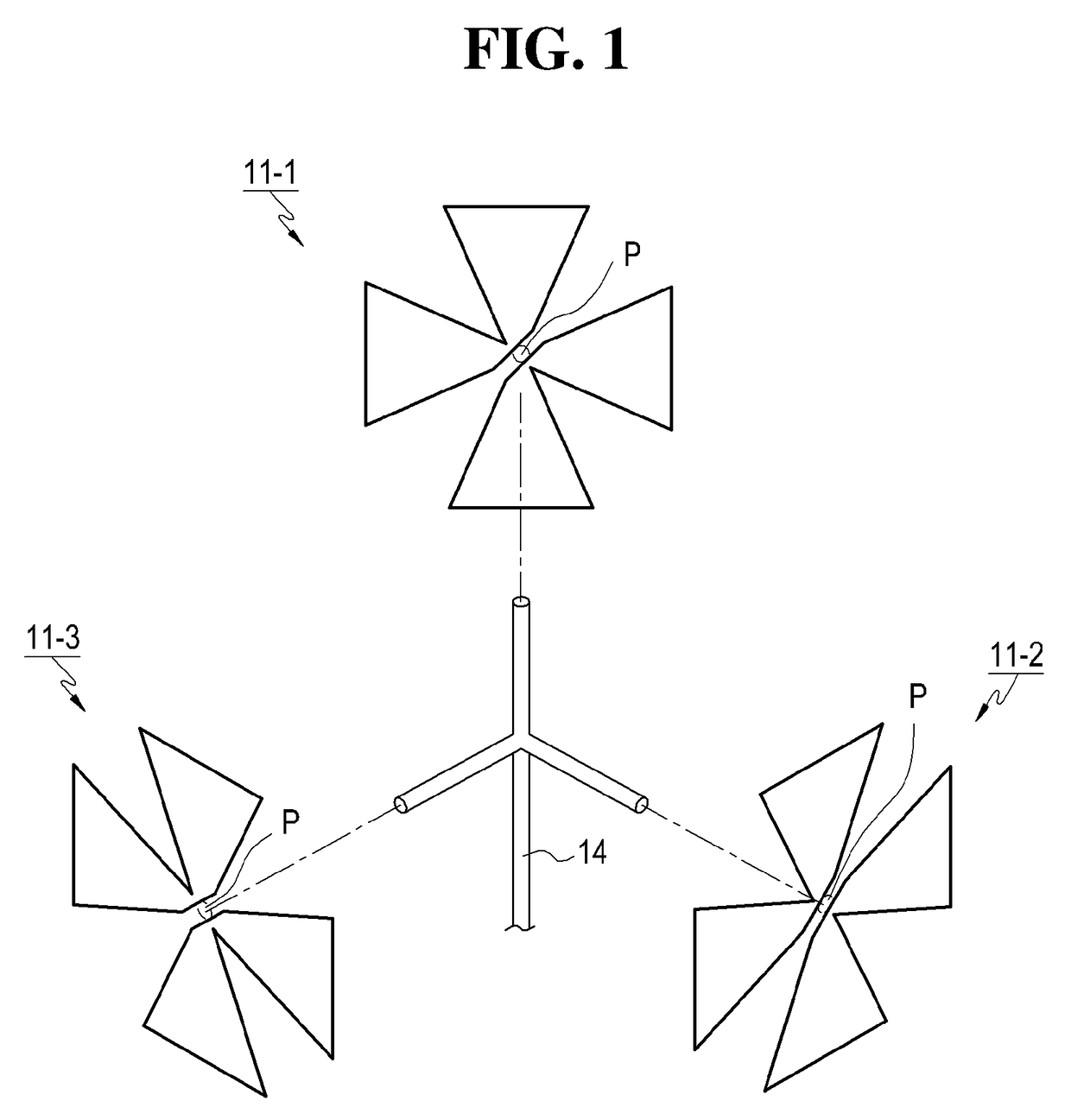
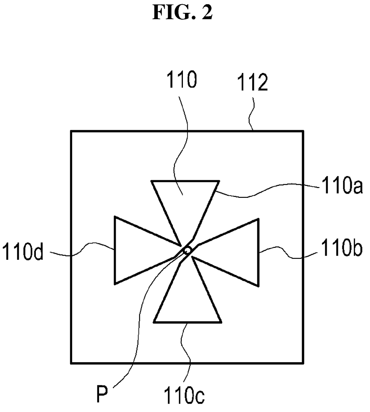
[0042]FIG. 1 is a schematic exploded view illustrating a structure of an omnidirectional antenna for a mobile communication service according to the present invention, and FIG. 2 is a view illustrating a first type structure of each of first to third radiation elements. Referring to FIGS. 1 and 2, an omnidirectional antenna according to the present invention may be implemented in a combination structure of, for example, three radiation elements (i.e., first to third radiation elements 11 (11-1, 11-2, and 11-3).

[0043]Referring to FIGS. 1 and 2, each of the radiation patterns 110 of the first to third radiation elements 11 has a combination structure of a horizontal polarization (H-pol) radiation unit having two radiation arms 110b and 110d and a vertical polarization (V-pol) dipole radiation unit having two radiation arms 110a and 110c. At this time, in each of the radiation elements 11, the one radiation arm 110d of the horizontal polarization dipole radiation unit and the one radia...

second embodiment

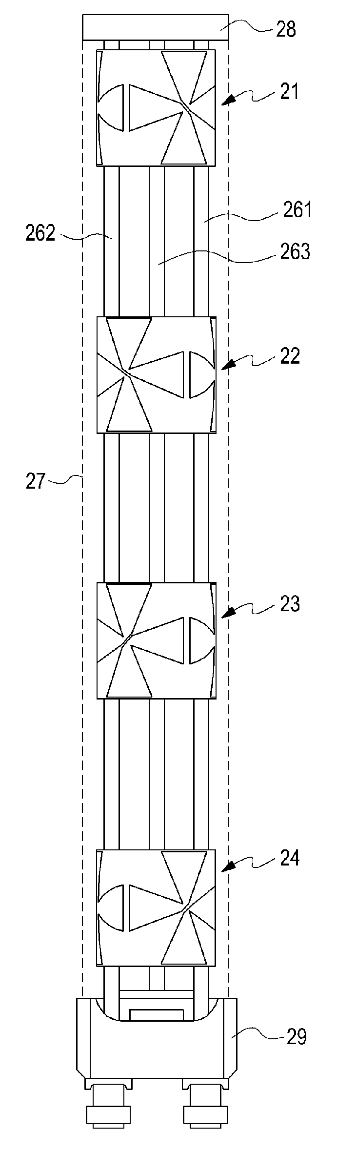
[0057]That is, the omnidirectional antenna according to the present invention may be configured by continuously arranging first to fourth radiation element arrays 21, 22, 23, and 24 in the vertical direction. At this time, the first and second radiation element arrays 21 and 22 may be constituted with the second type radiation elements illustrated in FIG. 3, and may have a configuration that omnidirectionally generates −45 degree polarization. In addition, the third and fourth radiation element arrays 23 and 24 may be constituted with the first type radiation elements illustrated in FIG. 2, and may have a configuration that omnidirectionally generates +45 degree polarization.

[0058]Accordingly, as illustrated in FIG. 7, the omnidirectional antenna according to the second embodiment of the present invention is configured such that the −45 degree polarization generated in the first and second radiation element arrays 21 and 22 and the +45 degree polarization generated in the third and ...


PUM


Abstract

The present invention relates to an omnidirectional antenna for a mobile communication service, comprising: a plurality of radiation elements disposed on a horizontal surface with a mutually same angle so as to respectively radiate beams; and a power supply unit for distributing and providing a power supply signal to each of the plurality of radiation elements, wherein each of the plurality of radiation elements has a structure in which a horizontal polarization dipole radiation unit having two radiation arms is coupled to a vertical polarization dipole radiation unit having two radiation arms.

Description

CROSS REFERENCE TO RELATED APPLICATIONS[0001]This application is a continuation of an International Application No. PCT / KR2015 / 007548 filed on Jul. 21, 2015, which claims priority to Korean Patent Application No. 10-2014-0109486 filed on Aug. 22, 2014, the entire disclosures of which are incorporated herein by reference.TECHNICAL FIELD[0002]The present invention relates to an antenna that is applicable to a base station or a relay station in a mobile communication (PCS, cellular, CDMA, GSM, LTE, or the like) network, and in particular, to an omnidirectional antenna.BACKGROUND ART[0003]An omnidirectional antenna, called a non-directional antenna, is an antenna designed to radiate electromagnetic waves uniformly all around 360 degrees in the horizontal direction. In a mobile communication network, it is impossible to predict a direction where a mobile communication terminal moves due to a characteristic thereof. Thus, the mobile communication terminal is typically provided with an omn...

Claims


Application Information

Patent Timeline
IPC IPC(8): H01Q1/24H01Q9/18H01Q9/06H01Q21/24H01Q1/48H01Q1/36
CPCH01Q1/36H01Q9/065H01Q1/48H01Q9/18H01Q1/246H01Q21/24H01Q9/285H01Q21/205H01Q21/26
Inventor MOON, YOUNG-CHANCHOI, OH-SEOGKIM, IN-HOYANG, HYOUNG-SEOK
Owner KMW INC
Why Eureka
Try Eureka