
Gyroscope with auxiliary self-test

a gyroscope and self-testing technology, applied in the direction of speed measurement using gyroscopic effects, instruments, surveying and navigation, etc., can solve the problems of measurement errors, gyroscope gain may differ from expected gain, and gyroscope gain may chang

Active Publication Date: 2017-06-15
PANASONIC CORP
View PDF4 Cites 6 Cited by
  • Summary
  • Abstract
  • Description
  • Claims
  • Application Information

AI Technical Summary

Benefits of technology

The patent describes a system and method for testing a gyroscope's ability to detect rotation. The system includes a drive circuit that causes the sensors to oscillate at a specific frequency, while the sensors rotate around an axis perpendicular to the device plane. The system also includes sensors that change their voltage based on the movement of the sensors. An auxiliary electrode set is also included to drive the sensors at different frequencies and measure the resulting changes in voltage. The system can identify any failures in the gyroscope based on the voltage measurements. The technical effect of this patent is to provide a reliable and efficient way to test the quality and functionality of gyroscopes.

Problems solved by technology

If these parameters do not match the designed parameters (e.g., as a result of variances in manufacturing), the gain of the gyroscope may differ from an expected gain, which may result in measurement errors.
As components wear over time, or if components are damaged, the gain of the gyroscope may change.

Method used


Image

  • Gyroscope with auxiliary self-test
  • Gyroscope with auxiliary self-test
  • Gyroscope with auxiliary self-test

Examples


Embodiment Construction

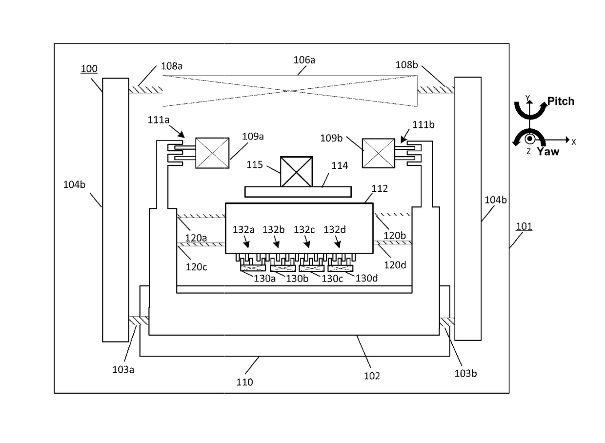
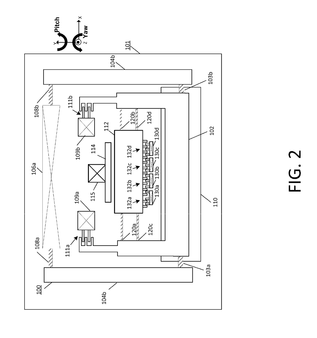
[0016]A MEMS gyroscope may be designed to have a drive mode resonant frequency and a sense mode resonant frequency. One or more masses of the MEMS gyroscope are driven at the drive mode resonant frequency, and based on the design and placement of springs that interconnect different masses, one or more sense oscillators (e.g., a sense mass, proof mass, Coriolis mass, or any suitable combination thereof) of the MEMS gyroscope may move in a sense direction in response to a Coriolis force caused by rotation of the gyroscope. The angular velocity of the rotation of the gyroscope may be determined based on the movement of a moving electrode of the sense mass relative to a fixed electrode, which may be measured at the drive frequency.

[0017]In an embodiment, the sense oscillator is also vibrated at a plurality of test frequencies (e.g., two test frequencies), for example, by additional auxiliary electrodes attached to the sense oscillator. The test frequencies are different from the drive f...


PUM


Abstract

A gyroscope includes drive electrodes that drive a drive mass at a drive frequency. A sense mass is responsive to a Coriolis force caused by rotation of the gyroscope and oscillates based on the drive frequency. Electrodes adjacent to the sense mass drive the sense mass at test frequencies. The response to the driving at the test frequencies is measured and a gyroscope failure is identified based on this response.

Description

BACKGROUND[0001]Numerous items such as smart phones, smart watches, tablets, automobiles, aerial drones, appliances, aircraft, exercise aids, and game controllers may utilize motion sensors during their operation. In many applications, various types of motion sensors such as accelerometers and gyroscopes may be analyzed independently or together in order to determine varied information for particular applications. For example, gyroscopes and accelerometers may be used in gaming applications (e.g., smart phones or game controllers) to capture complex movements by a user, drones and other aircraft may determine orientation based on gyroscope measurements (e.g., roll, pitch, and yaw), and vehicles may utilize measurements for determining direction (e.g., for dead reckoning) and safety (e.g., to recognizing skid or roll-over conditions).[0002]Many sensors such as accelerometers, gyroscopes, pressure sensors, and microphones are implemented as microelectromechanical systems (MEMS) sensor...

Claims


Application Information

Patent Timeline
Patent Type & Authority Applications(United States)
IPC IPC(8): G01C19/5719
CPCG01C19/5719G01C19/5762G01C19/5733G01C19/5776G01C19/5783
Inventor CORONATO, LUCAGAFFORELLI, GIACOMORUOHIO, JAAKKO
Owner PANASONIC CORP
Learn More