
Planning and guiding method and excavation guiding device for correctly implanting artificial tooth root at predetermined site

a predetermined site and excavation technology, applied in the field of planning and guiding methods and excavation guiding devices, can solve the problems of ineffective dental implants, the tendency of drills or implants used in excavation and in the course of implantation to tilt and shift toward the low-resistance buccal side, and the placement of implants at the planned ideal site is rar

Inactive Publication Date: 2017-06-15
LIU EN HENG
View PDF0 Cites 4 Cited by
  • Summary
  • Abstract
  • Description
  • Claims
  • Application Information

AI Technical Summary

Benefits of technology

The objective of this patent is to ensure that the implanted artificial tooth root is stable and secure at the beginning.

Problems solved by technology

Although conventional implantation techniques are advantageously stable, safe, and conducive to long-term efficacy as well as esthetic enhancement, incorrect sites of implantation render dental implants ineffective.
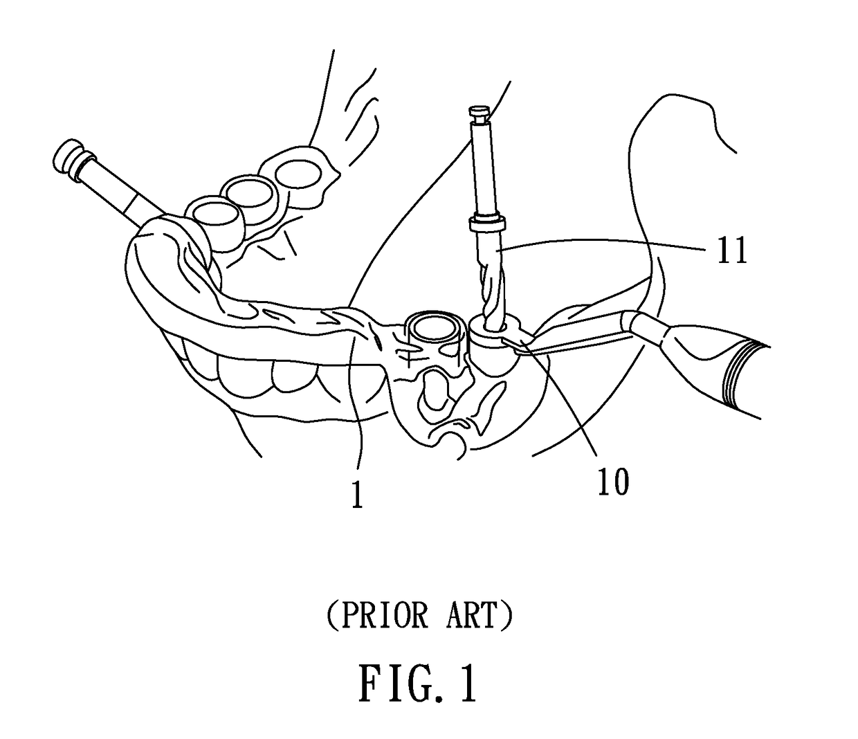
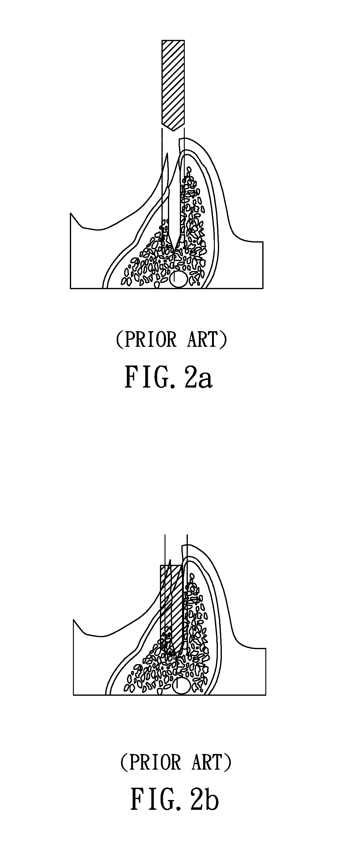
The aforesaid guidance is reliable when performed on a flat homogeneous alveolar bone; however, After tooth extraction, the thin buccal portion of the alveolar ridge is absorbed and therefore disappears in several months; as a result, dental implant surgery is often confronted with an alveolar ridge with a low buccal side and a high lingual side, and therefore the drill or implant used in the course of excavation and in the course of implantation is likely to tilt and shift toward the low-resistance buccal side, and in consequence the implant is seldom placed at a planned ideal site.
Although a small-diameter drill is able to align itself with a predetermined excavation axis during the early phase of reaming, a large-diameter drill introduced into the middle and late phases of reaming is likely to tilt toward the low-resistance side in the course of excavation even when guided by the drill guiding ring, due to the aforesaid problem with an alveolar ridge.

Method used


Image

  • Planning and guiding method and excavation guiding device for correctly implanting artificial tooth root at predetermined site
  • Planning and guiding method and excavation guiding device for correctly implanting artificial tooth root at predetermined site
  • Planning and guiding method and excavation guiding device for correctly implanting artificial tooth root at predetermined site

Examples


Embodiment Construction

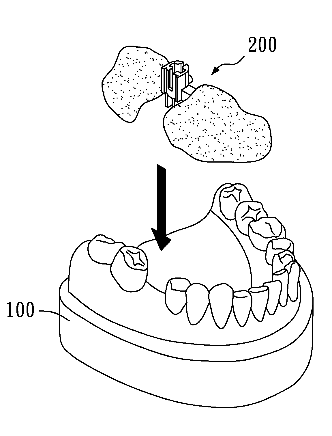
[0031]The initial stability of an implant and whether the implant is actually placed at a planned ideal site correlate significantly with the excavation pattern and the bone pattern of the alveolar bone. In view of this, the present invention discloses a planning and guiding method and excavation guiding device for carrying out excavation at an excavation site subjected to lateral shift and stage-based guidance.

[0032]The human jawbone is formed from two types of osseous tissue, namely cortical bone and spongy bone. Cortical bone, which forms the outer shell of the bone, is dense and hard. Spongy bone, which forms the core of the bone, is less dense and softer. A guiding ring site of the present invention is designed according to a planned predetermined site of an implant. The adjective “stage-based” (also known as “two-stage”) is descriptive of the two-stage guidance which takes place at a cortical bone section and a spongy bone section. The eccentric excavation of the cortical bone...


PUM


Abstract

A planning and guiding method and excavation guiding device correctly implant an artificial tooth root at a predetermined site, perform various excavation processes on a cortical bone section and a spongy bone section by stage-based guidance, and guide eccentric excavation of the cortical bone section and concentric excavation of the spongy bone section according to a bone pattern, such that the artificial tooth root thus implanted is not only positioned at a planned ideal site but also manifests appropriate initial stability.

Description

FIELD OF THE INVENTION[0001]The present invention relates to planning and guiding methods and excavation guiding devices for use with an artificial tooth root and more particularly to a planning and guiding method and excavation guiding device for correctly implanting an artificial tooth root at a predetermined site.BACKGROUND OF THE INVENTION[0002]Dental implant surgery is a procedure that implants an artificial tooth root in the jawbone and then mounts an artificial crown on the artificial tooth root so that the prosthetic tooth not only looks attractive but is also effective in chewing. Although conventional implantation techniques are advantageously stable, safe, and conducive to long-term efficacy as well as esthetic enhancement, incorrect sites of implantation render dental implants ineffective.[0003]A conventional implantation guiding device performs a tomography scan on the jawbone, creates a virtual implantation site in a 3D image with computer software, plans a drill guidi...

Claims


Application Information

Patent Timeline
IPC IPC(8): A61C1/08A61C8/00
CPCA61C8/0089A61C1/084
Inventor LIU, EN-HENG
Owner LIU EN HENG
Learn More