Connector housing

Active Publication Date: 2017-06-08
YAZAKI CORP
View PDF4 Cites 0 Cited by
  • Summary
  • Abstract
  • Description
  • Claims
  • Application Information

AI Technical Summary

Benefits of technology

The invention aims to prevent foreign substances, such as cables or other objects, from getting caught between the curved portion of the housing and the swinging portion of the fitting operation lever. This could cause damage or detachment of the fitting operation lever. The invention's design includes a rib on the housing's side surface that blocks the gap between the curved portion and the swinging portion, preventing foreign substances from entering and causing issues. Additionally, the rib's outer edge is positioned to make it difficult for foreign substances to move around and enter the gap, further preventing damage or detachment of the fitting operation lever.

Problems solved by technology

According to the above configuration, even when a foreign substance such as a cable tends to enter a gap between the curved portion of the side surface of the housing body and the swinging portion of the fitting operation lever, the foreign substance interferes with the rib provided in the curved portion of the side surface of the housing body.

Method used


Image

  • Connector housing
  • Connector housing
  • Connector housing

Examples


first embodiment

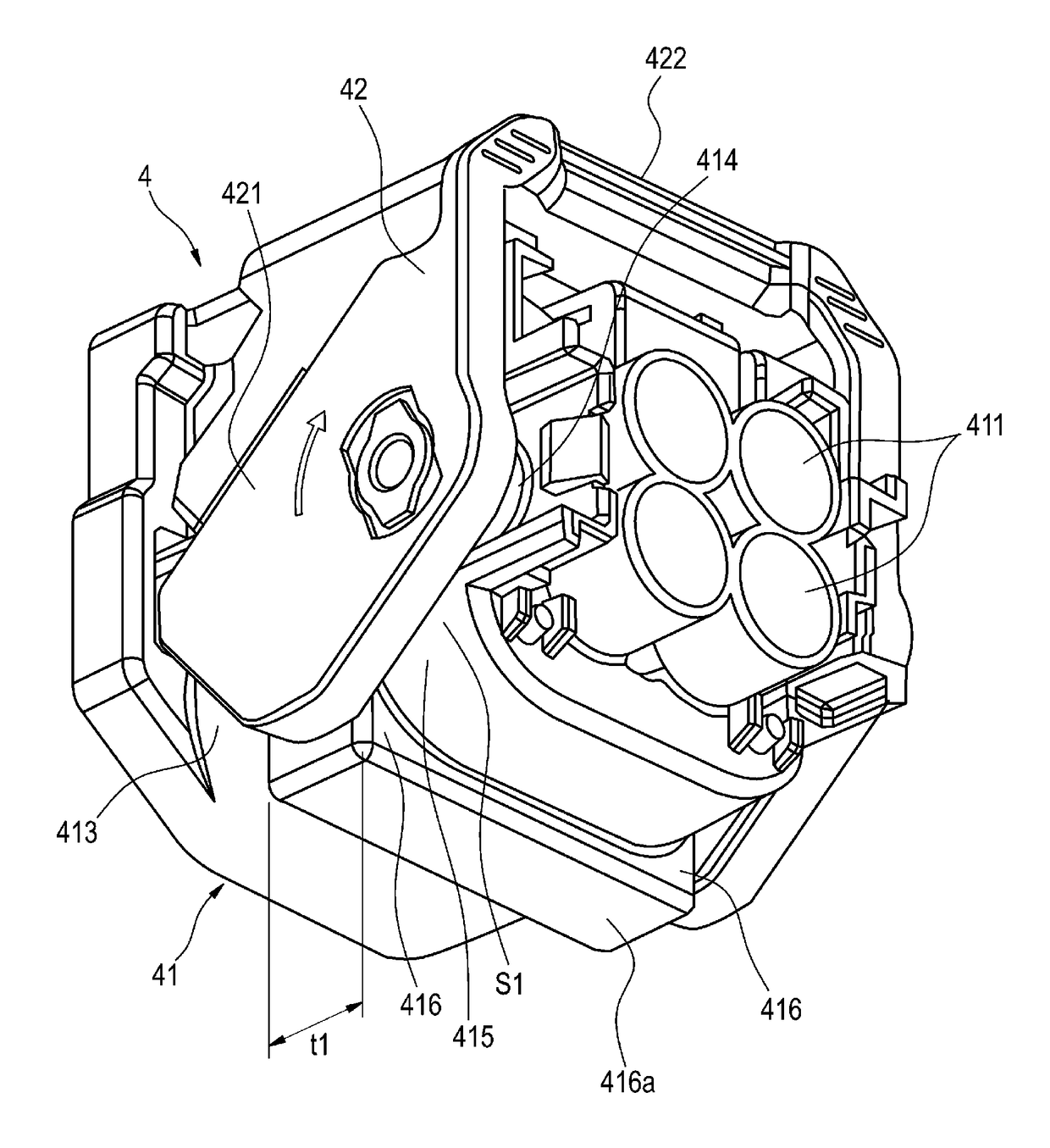
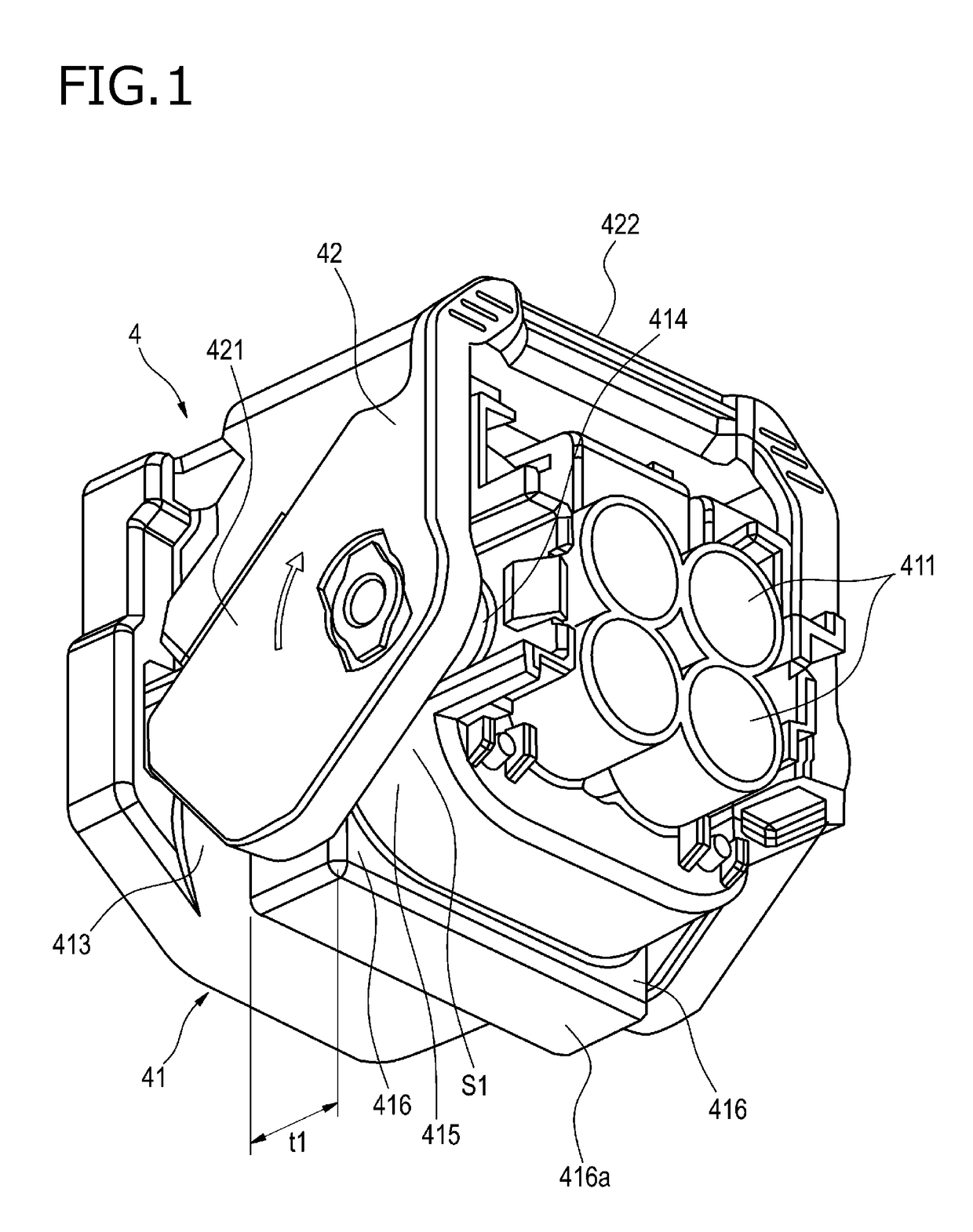
[0037]FIG. 1 and FIG. 2 show a first embodiment of a connector housing according to the invention. FIG. 1 is a perspective view of the connector housing according to the first embodiment of the invention, as seen obliquely from behind and below. FIG. 2 is a rear view of the connector housing shown in FIG. 1.

[0038]The connector housing 4 according to the first embodiment includes a housing body 41 and a fitting operation lever 42. The fitting operation lever 42 is attached to opposite side surfaces of the housing body 41 rotatably.

[0039]The housing body 41 includes terminal receiving holes that are disposed therein in two rows and two columns. Cables inserting holes 411 are disposed in two rows and two columns in a rear end of the housing body 41 so that cables connected to terminal fittings received in the terminal receiving holes are inserted into the cable inserting holes 411.

[0040]Lever supporting portions 414 are provided in the side surfaces 413 of the housing body 41 so that t...

second embodiment

[0049]FIG. 3 and FIG. 4 show a second embodiment of a connector housing according to the invention. FIG. 3 is a perspective view of the connector housing according to the second embodiment of the invention, as seen obliquely from behind and below. FIG. 4 is a rear view of the connector housing shown in FIG. 3.

[0050]In the connector housing 4A according to the second embodiment, the first embodiment is changed partially so that an outer edge portion 416a extending in a housing width direction of each rib 416 and an outer circumferential edge 421a of each swinging portion 421 can be arranged to be flush with each other. That is, the rib 416 according to the second embodiment has a shorter protruding length in a housing height direction by a height h than the rib 416 according to the first embodiment.

[0051]Also in the connector housing 4A according to the second embodiment, a gap S1 between a curved portion 415 of each side surface 413 of a housing body 41 and a corresponding swinging ...


PUM


Abstract

A connector housing includes a housing body and a fitting operation lever that has a swinging portion attached to the housing body rotatably. A part of the rib protruding toward the swinging portion narrows an interval between a curved portion of the housing body and the swinging portion to a predetermined value or below. A part of the rib protruding toward a direction separating from a lower surface of the housing body has a flat face. A distance between the rotary axis of the swinging portion and the flat face is larger than a distance between the rotary axis and a part of an outer circumferential edge of the swinging portion.

Description

CROSS REFERENCE TO RELATED APPLICATION[0001]This application is a continuation of PCT application No. PCT / JP2015 / 077371, which was filed on Sep. 28, 2015 based on Japanese Patent Application (No. 2014-199127) filed on Sep. 29, 2014, the contents of which are incorporated herein by reference. Also, all the references cited herein are incorporated as a whole.BACKGROUND[0002]1. Technical Field[0003]The present invention relates to a connector housing that includes a housing body and a fitting operation lever for fitting the housing body and a mating housing body to each other.[0004]2. Background Art[0005]In the background art, there have been proposed connector housings including fitting operation levers. For example, as shown in FIG. 7, one (hereinafter referred to as “background-art housing 100”) of the background-art connector housings includes a housing body 110 and a fitting operation lever 120. The housing body 110 receives terminal fittings connected to end portions of cables 21...

Claims


Application Information

Patent Timeline
IPC IPC(8): H01R13/639
CPCH01R13/639H01R13/62933
Inventor SUZUKI, SHOGOKANDA, HIDENORIHASEGAWA, TAKUYA
Owner YAZAKI CORP
Why Eureka
Try Eureka