
Bucket handle assembly

a bucket and handle technology, applied in the field of buckets or pails, can solve the problems of bucket sides collapsing inwardly, plastic cracking and failing around the bucket handle, adding machining and assembly costs,

Active Publication Date: 2017-06-08
FOSTER NORMAN
View PDF3 Cites 1 Cited by
  • Summary
  • Abstract
  • Description
  • Claims
  • Application Information

AI Technical Summary

Benefits of technology

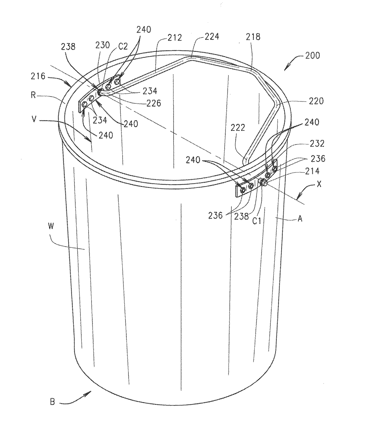
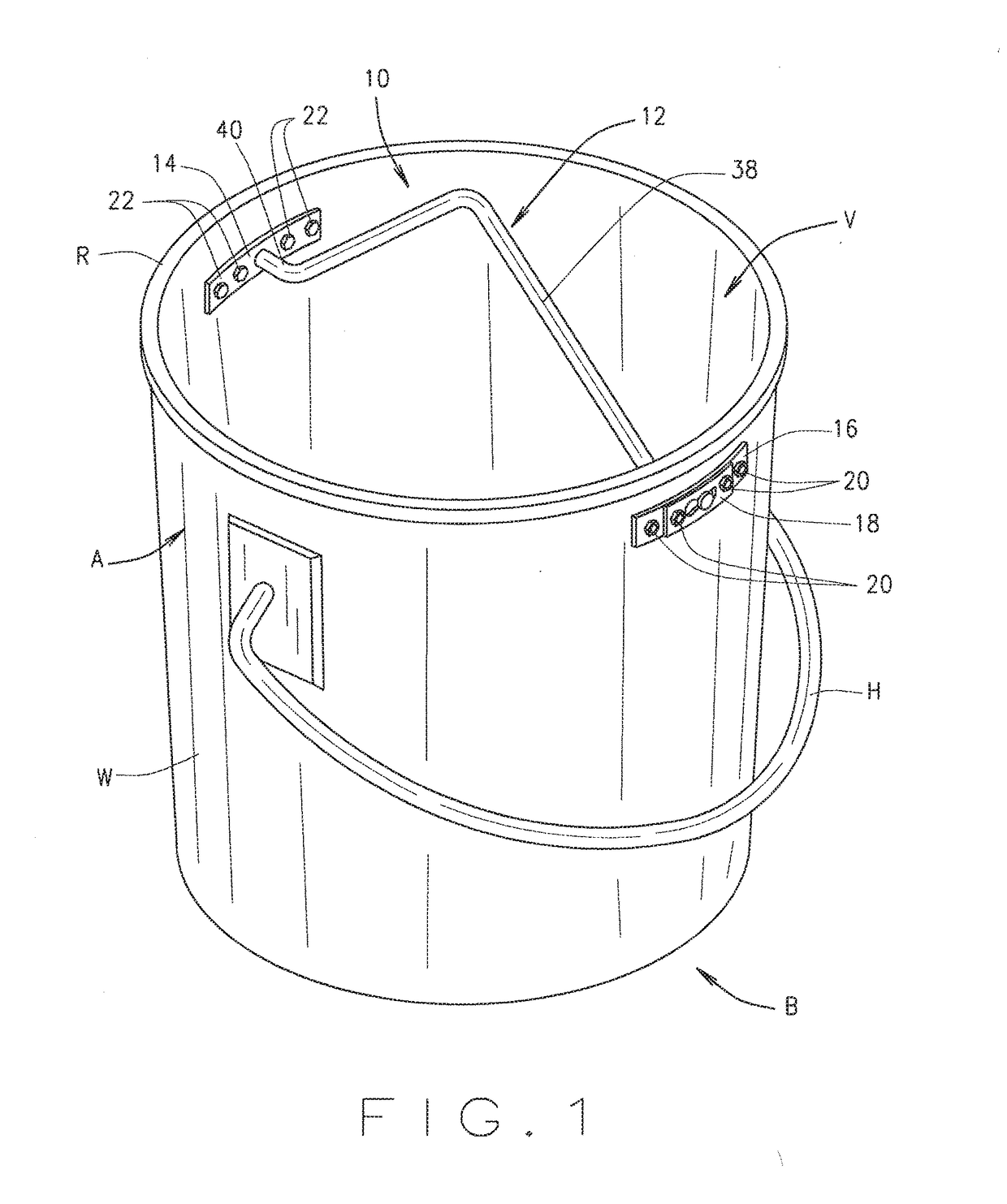
The invention is an improved handle and handle assembly for window washer's buckets. The handle is designed to be easier to assemble, cost-effective, and safer for window washers. The handle is attached to the inner surface of the bucket, allowing for easy placement and securing of a bucket lid to the bucket's upper lip. The handle is designed to freely rotate about the bucket, eliminating rotational torque and allowing for a natural equilibrium. The technical effects of this invention include improved safety, cost-effectiveness, and ease of assembly.

Problems solved by technology

Furthermore, the weight of the liquid in the bucket can cause the handle to pull out or deform the handle or cause the plastic to crack and fail around the handle.
Since conventional handles are mounted on the outside of the bucket, the weight of the liquids in the bucket can cause the sides of the bucket to collapse inwardly at the points where the handle is mounted to the bucket.
However, the bucket handle design of U.S. Pat. No. 6,352,169 and similar designs require that the handle be secured to the bucket with a nut and threaded shaft configuration that adds machining and assembly costs.
In addition, these configurations require means to ensure that the nut does not loosen or fall free from the handle, which could cause the bucket to tip or spill during use.
Unfortunately, the bucket handle design of U.S. Pat. No. 6,352,169 and similar designs hamper the rotation of the bucket relative to the handle at the handle mounts.
Unfortunately, bucket handles that are attached to the inner surface of a bucket, such as for example the handle of U.S. Pat. No. 6,352,169, interfere with and preclude the placement and securing of a bucket lid to the bucket's upper lip.

Method used


Image

  • Bucket handle assembly
  • Bucket handle assembly
  • Bucket handle assembly

Examples


Embodiment Construction

[0030]While the invention will be described and disclosed here in connection with certain preferred embodiments, the description is not intended to limit the invention to the specific embodiments shown and described here, but rather the invention is intended to cover all alternative embodiments and modifications that fall within the spirit and scope of the invention as defined by the claims included herein as well as any equivalents of the disclosed and claimed invention.

[0031]When describing elements or features and / or embodiments thereof, the articles “a”, “an”, “the”, and “said” are intended to mean that there are one or more of the elements or features. The terms “comprising”, “including”, and “having” are intended to be inclusive and mean that there may be additional elements or features beyond those specifically described.

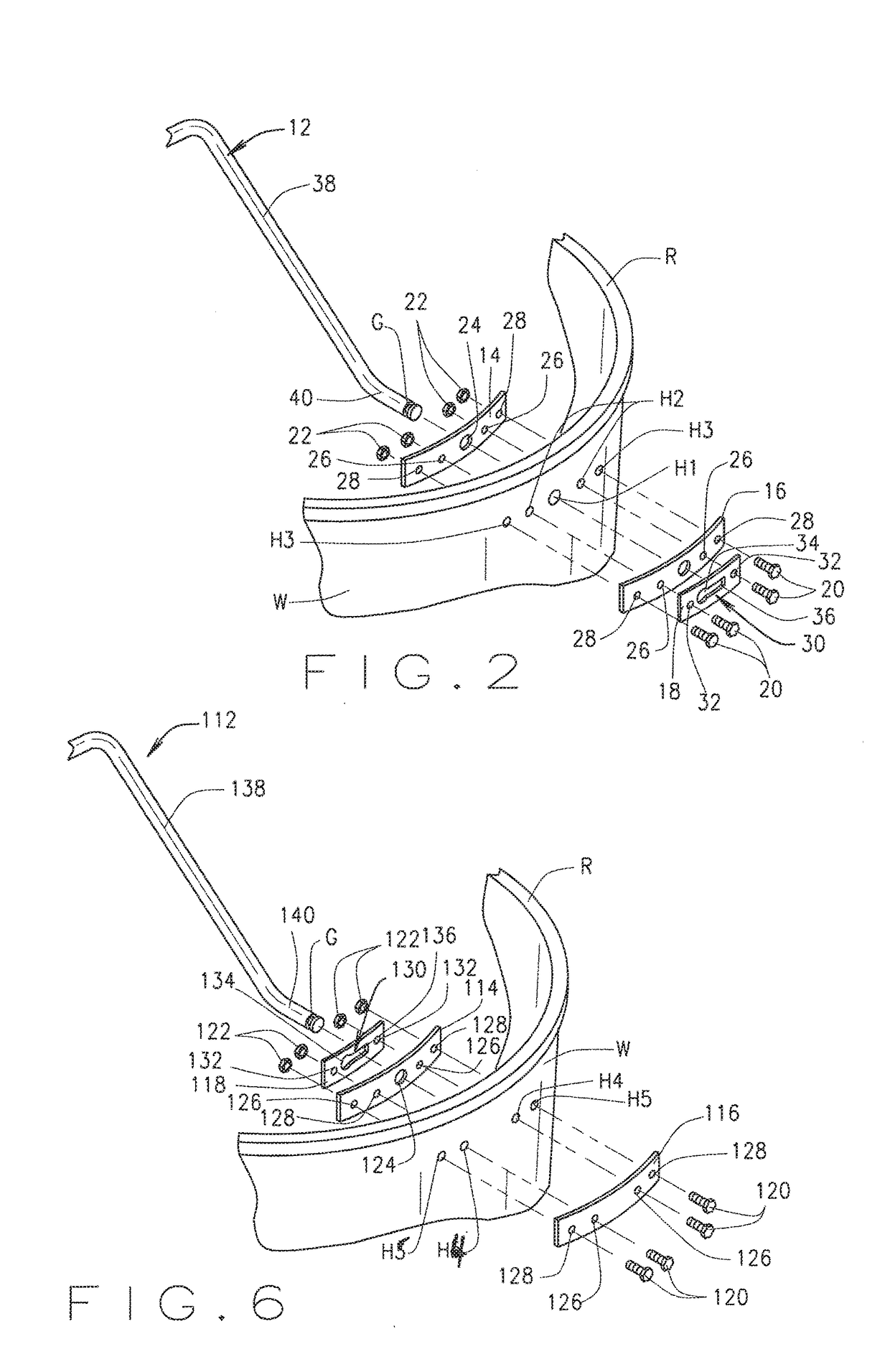
[0032]In referring to the drawings, a first representative embodiment of the novel bucket handle assembly 10 of the present invention is shown generally in F...


PUM


Abstract

A handle and assembly for a bucket. The bucket has first and second attachment regions on the inner surface of the sidewall near the rim. The sidewall has a compressed condition in which compressive forces are applied to opposite sides to reduce the distance between the attachment regions, and a relaxed condition with forces. The handle has attachment ends with an axis between them. The attachment ends attach to the attachment regions such that the handle rotates about the axis and can also move laterally along the axis. The handle has a first rotational position in which the handle is above the rim, and a second rotational position in which the handle is below the rim. The handle cannot rotate between the first and second positions when the sidewall is relaxed, but can when the sidewall is laterally compressed.

Description

CROSS REFERENCE TO RELATED APPLICATIONS[0001]This application derives and claims priority from U.S. provisional application 62 / 262,554 filed Dec. 3, 2015 and U.S. provisional application 62 / 297,413 filed Feb. 19, 2016, both of which U.S. provisional applications are incorporated herein by reference.STATEMENT REGARDING FEDERALLY SPONSORED RESEARCH OR DEVELOPMENT[0002]Not applicable.BACKGROUND OF THE INVENTION[0003]The invention is related generally to buckets or pails and, more specifically, to an improved handle and handle assembly comprising the handle and an associated attachment apparatus, the attachment apparatus designed for connecting the handle to a bucket or pail, particularly a bucket used by window cleaners on high-rise buildings.[0004]Buckets or pails with handles are known to the art. However, those persons employed as window cleaners or window washers on high rise buildings use buckets containing cleaning liquid or water that must meet certain requirements of the trade....

Claims


Application Information

Patent Timeline
IPC IPC(8): B65D25/32
CPCB65D2525/285B65D25/32B65D2525/288
Inventor FOSTER, NORMAN
Owner FOSTER NORMAN
Learn More