
Stove Top Fire Extinguishing Device

a stovetop fire and fire extinguishing technology, applied in fire rescue and other directions, can solve the problems of microwave without any inner recess, full-fledged house fire, fire damage, etc., to reduce the visibility of fire extinguishing devices, increase the aesthetic appearance of kitchen units, and reduce the encroachment of such devices.

Active Publication Date: 2017-06-08
SUPPRESSOR LLC
View PDF0 Cites 1 Cited by
  • Summary
  • Abstract
  • Description
  • Claims
  • Application Information

AI Technical Summary

Benefits of technology

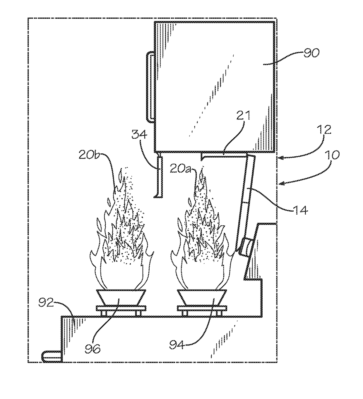
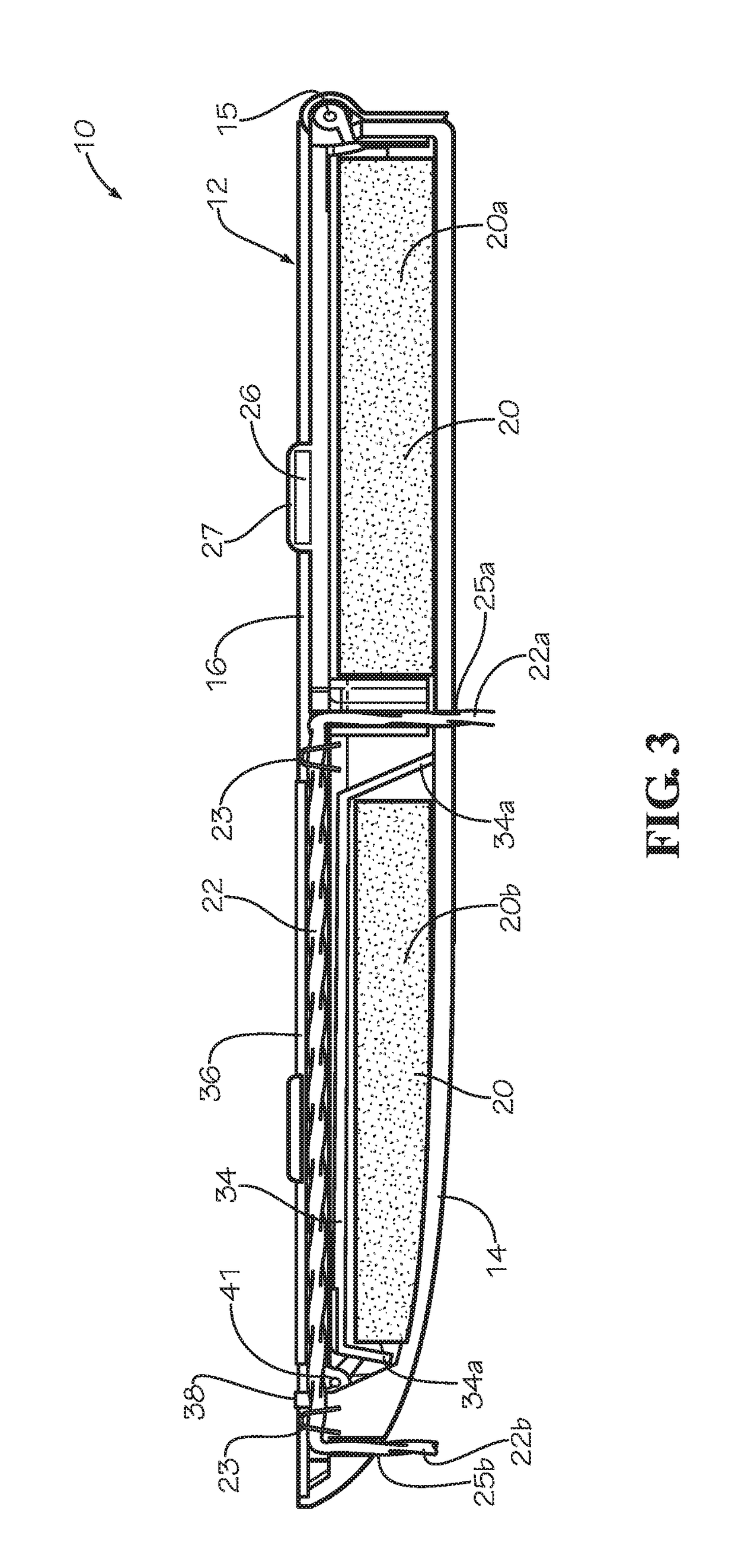
[0012]In some embodiments, the projection member can be biased toward the extended position, for instance by a torsion spring. In other embodiments, the container can include a frame, the cover pivotally connected to the frame and rotatable with respect to the frame between an open and a closed position. In some embodiments, the heat responsive actuator can be engageable with the closure of the container to retain the closure in the closed position and the projection member in the retracted position such that the fire suppressant material can be retained within the container. The heat responsive actuator can then be actuated by a fire on the stovetop to release the cover, the projection member, and the fire suppressant material. In still other embodiments, the fire can be located on a second burner of the stovetop, and the heat responsive actuator can be positionable to be actuated by the fire on the second burner when the container is mounted to the microwave.
[0014]Another objective of the present disclosure is to help reduce the visibility of fire extinguishing devices positioned below microwaves and reduce the encroachment of such devices in the cooking space of the user.
[0015]Another objective is to help increase the aesthetic appearance of a kitchen unit including a stove, a microwave, and a fire extinguishing device.

Problems solved by technology

Grease fires grow rapidly and can quickly cause fire damage to nearby cabinetry and kitchen structures, and can eventually lead to full fledge house fires if they are not put out in time.
In such kitchens with hoods, the fire prevention devices can be positioned in the recess of the hood such that the devices are not readily visible to an observer of the kitchen unit.
However, in more recent years it has become increasingly common, especially in large apartment and condo complexes, for the kitchen to include a microwave above the stovetop for space saving reasons, the microwave lacking any inner recess to position fire prevention devices.
Some conventional devices may also undesirably extend into a user's cooking space below the microwave because of their size and height.
Additionally, many conventional microwaves to do not extend over a front burner on the stovetop, such that conventional devices capable of extinguishing fires on a front burner of the stovetop undesirably extend outward from the microwave, further decreasing the aesthetic appearance of the devices.
Furthermore, some conventional devices are of such a large size and weight that the devices must be mounted directly to a wall adjacent and beneath the microwave, which is undesirable.
The size and unaesthetic appearance of conventional devices can force a builder to have to choose between aesthetics and safety, often times the builder choosing aesthetics to ensure sales of the living units.
Additionally, even if builders choose to include conventional fire prevention devices in their properties, the resident once occupying the apartment or living space often chooses to remove the fire prevention device for aesthetic reasons.
As such, the unaesthetic appearance of conventional devices can deter proper use of such devices, which can ultimately decrease the safety of the kitchen and increase the likelihood of a stovetop fire outbreak spreading to nearby fixtures, which is undesirable.

Method used


Image

  • Stove Top Fire Extinguishing Device
  • Stove Top Fire Extinguishing Device
  • Stove Top Fire Extinguishing Device

Examples


Embodiment Construction

[0036]While the making and using of various embodiments of the present invention are discussed in detail below, it should be appreciated that the present invention provides many applicable inventive concepts that are embodied in a wide variety of specific contexts. The specific embodiments discussed herein are merely illustrative of specific ways to make and use the invention and do not delimit the scope of the invention. Those of ordinary skill in the art will recognize numerous equivalents to the specific apparatus and methods described herein. Such equivalents are considered to be within the scope of this invention and are covered by the claims.

[0037]In the drawings, not all reference numbers are included in each drawing, for the sake of clarity. In addition, positional terms such as “upper,”“lower,”“side,”“top,”“bottom,” etc. refer to the apparatus when in the orientation shown in the drawing. A person of skill in the art will recognize that the apparatus can assume different or...


PUM


Abstract

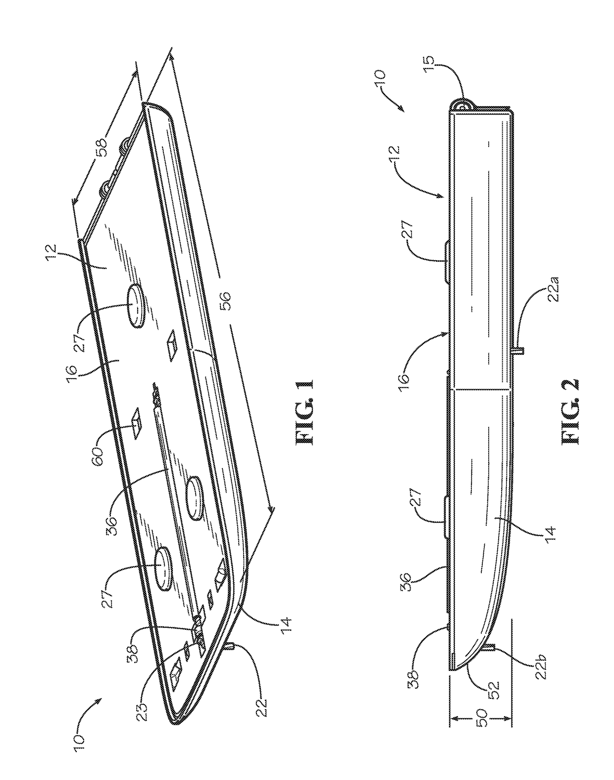
An apparatus for extinguishing a stovetop fire including a container detachably mountable to a microwave positioned above the stove top, the container having a closure retained in a closed position on the container. A projection member is connected to the container, the projection member retained in a retracted while the closure is in the closed position. A supply of fire suppressant material is retained within the container when the closure is in the closed position, the supply of fire suppressant material including a second burner portion positioned against the projection member. A heat responsive actuator is disposed on the container. When the container is mounted to the microwave over a first burner, and the fire actuates the heat responsive actuator, the closure moves to an open position and the projection member moves to an extended position, the projection member forcing the second burner portion toward the second burner.

Description

CROSS-REFERENCES TO RELATED APPLICATIONS[0001]This application is a continuation of U.S. patent application Ser. No. 15 / 276,741 filed Sep. 26, 2016 entitled Stove Top Fire Extinguishing Device, which claims benefit of U.S. Provisional Patent Application Ser. No. 62 / 254,252 filed Nov. 12, 2015 entitled STOVE TOP FIRE EXTINGUISHING DEVICE which is herein incorporated by reference in its entirety.[0002]A portion of the disclosure of this patent document contains material that is subject to copyright protection. The copyright owner has no objection to the reproduction of the patent document or the patent disclosure, as it appears in the U.S. Patent and Trademark Office patent file or records, but otherwise reserves all copyright rights whatsoever.STATEMENT REGARDING FEDERALLY SPONSORED RESEARCH OR DEVELOPMENT[0003]Not ApplicableREFERENCE TO SEQUENCE LISTING OR COMPUTER PROGRAM LISTING APPENDIX[0004]Not ApplicableBACKGROUND OF THE INVENTION[0005]The present disclosure relates generally t...

Claims


Application Information

Patent Timeline
Patent Type & Authority Applications(United States)
IPC IPC(8): A62C3/00A62C37/08A62C35/13
CPCA62C3/006A62C35/13A62C37/08A62C35/02A62C37/00A62C37/12A62C99/0045
Inventor SCAROLA, RICKBERRY, JOHNSEEMAN, DAVEREESE, EVAN
Owner SUPPRESSOR LLC
Learn More