
Waste management simulation system and method

a waste management and simulation system technology, applied in the field of waste management, can solve the problems of significant data acquisition and cleansing activities, time-consuming and expensive, and the building of new waste management facilities is generally a costly and slow process, and achieve the effect of defining the scope and granularity of the system

Inactive Publication Date: 2017-06-01
MANDALAY TECH
View PDF2 Cites 16 Cited by
  • Summary
  • Abstract
  • Description
  • Claims
  • Application Information

AI Technical Summary

Benefits of technology

The present invention is about simulation of waste management systems. It aims to overcome disadvantages or provide consumers with useful or commercial options.

Problems solved by technology

The building of new waste management facilities is generally an expensive and slow process.
Engagements are often undertaken by Request for Tender processes, which can be time consuming and expensive.
Furthermore, these engagements can involve significant data acquisition and cleansing activities due to the lack of consistent and current data sources.
A problem with modelling waste management systems according to the prior art is that the process is time consuming, and complex.
In particular, complexity is generally exponential with reference to the number of scenarios being simulated.
As such, modelling is expensive and generally restricted to a limited set of scenarios.
Furthermore, the collation and aggregation of multiple disparate data sources, and rationalisation of data and data anomalies is also generally complex.
Additionally, due to the complex and generally highly proprietary nature of the models of the prior art, it is very difficult for consultants to engage their customer in population of the model or the development of scenarios, particularly in real time.
Yet further again, due to nature of the data generated in the model, and the very complex nature of the systems this data represents, current approaches (i.e. spreadsheets) are unable to efficiently represent the outcome of modelling, making it difficult to communicate these outcomes.

Method used


Image

  • Waste management simulation system and method
  • Waste management simulation system and method
  • Waste management simulation system and method

Examples


Embodiment Construction

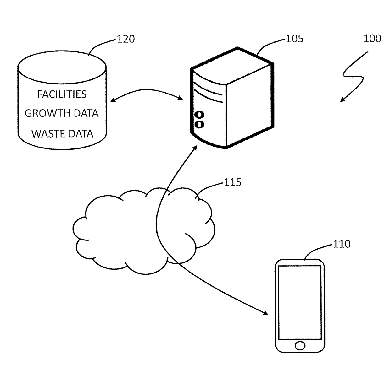
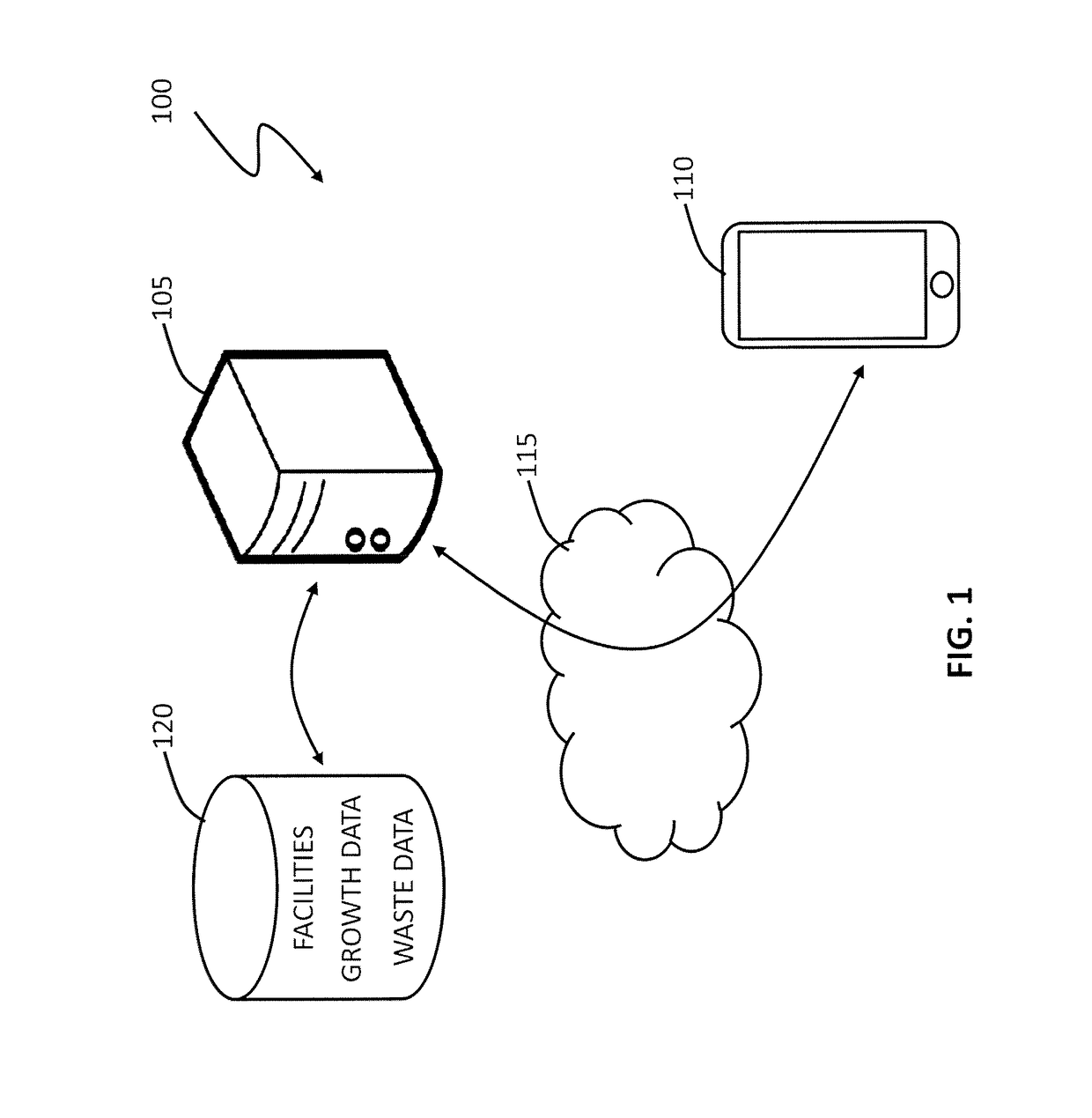
[0087]FIG. 1 illustrates a waste management simulation system 100, according to an embodiment of the present invention.

[0088]The waste management simulation system 100 includes a server 105, for providing a graphical user interface (GUI) to a user device 110, by a communications network 115, such as the Internet.

[0089]The server 105 is coupled to one or more data stores 120, which include waste input data, waste management facility data, and growth data. The skilled addressee will, however, appreciate that the waste input data, waste management facility data, and growth data can be provided by a user on demand, or determined at least partly according to parameters provided by the user.

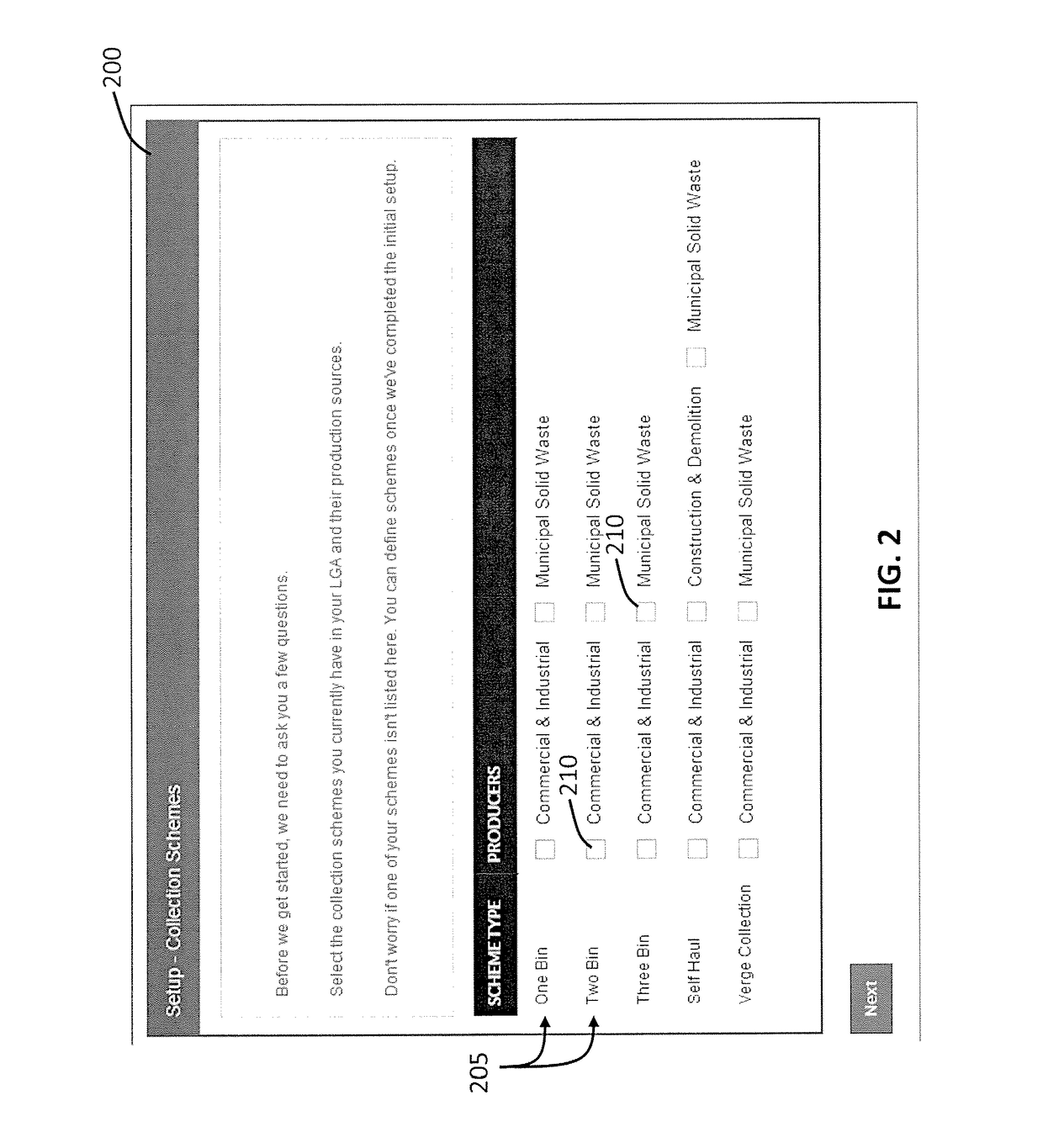
[0090]The GUI, described in further detail below, enables a user to interactively define a waste management model. The waste management model includes a plurality of waste inputs, defined according to the waste input data, and a plurality of waste management facilities, defined according to the waste m...


PUM


Abstract

A waste management simulation method and system is provided. The waste management simulation method includes: providing a graphical user interface for interactively defining a waste management model, wherein the model includes a plurality of waste inputs, a plurality of waste management facilities, and a plurality of waste streams connecting the waste inputs with the waste management facilities, and wherein the graphical user interface enables interactive definition of the waste streams; and determining at least one performance indicator of the model according to the defined waste management model and a forecast of the waste inputs.

Description

TECHNICAL FIELD[0001]The present invention relates to waste management and in particular, although not exclusively to simulation of waste management systems.BACKGROUND ART[0002]As populations grow, utilisation of waste management facilities, such as landfills and recycling stations, is generally increasing. Eventually, waste management facilities will reach a capacity, either in terms of processing capacity, or in terms of waste storage, as is generally the case for landfill sites.[0003]The building of new waste management facilities is generally an expensive and slow process. As such, it is desirable to know as early as possible when new facilities will reach capacity and / or will be required to meet emerging processing requirements. Waste management analysis and waste strategy simulation can be used to determine future needs of a waste management system.[0004]The calculation of performance of waste management facilities generally involves the collation and aggregation of multiple d...

Claims


Application Information

Patent Timeline
Patent Type & Authority Applications(United States)
IPC IPC(8): G06Q10/06G06Q10/00
CPCG06Q10/30G06Q10/0639Y02W90/00
Inventor KALINOWSKI, SIMONPERRIN, DARREN
Owner MANDALAY TECH
Learn More