
Swimming Speedometer System with Near-Eye Display

a speedometer and display technology, applied in underwater equipment, underwater equipment, instruments, etc., can solve the problems of swimmers not having both systems in swimming, denying swimmers the most effective method, and having little access to these measurements in training sessions

Active Publication Date: 2017-05-25
SWIMMETRIC LLC
View PDF6 Cites 10 Cited by
  • Summary
  • Abstract
  • Description
  • Claims
  • Application Information

AI Technical Summary

Benefits of technology

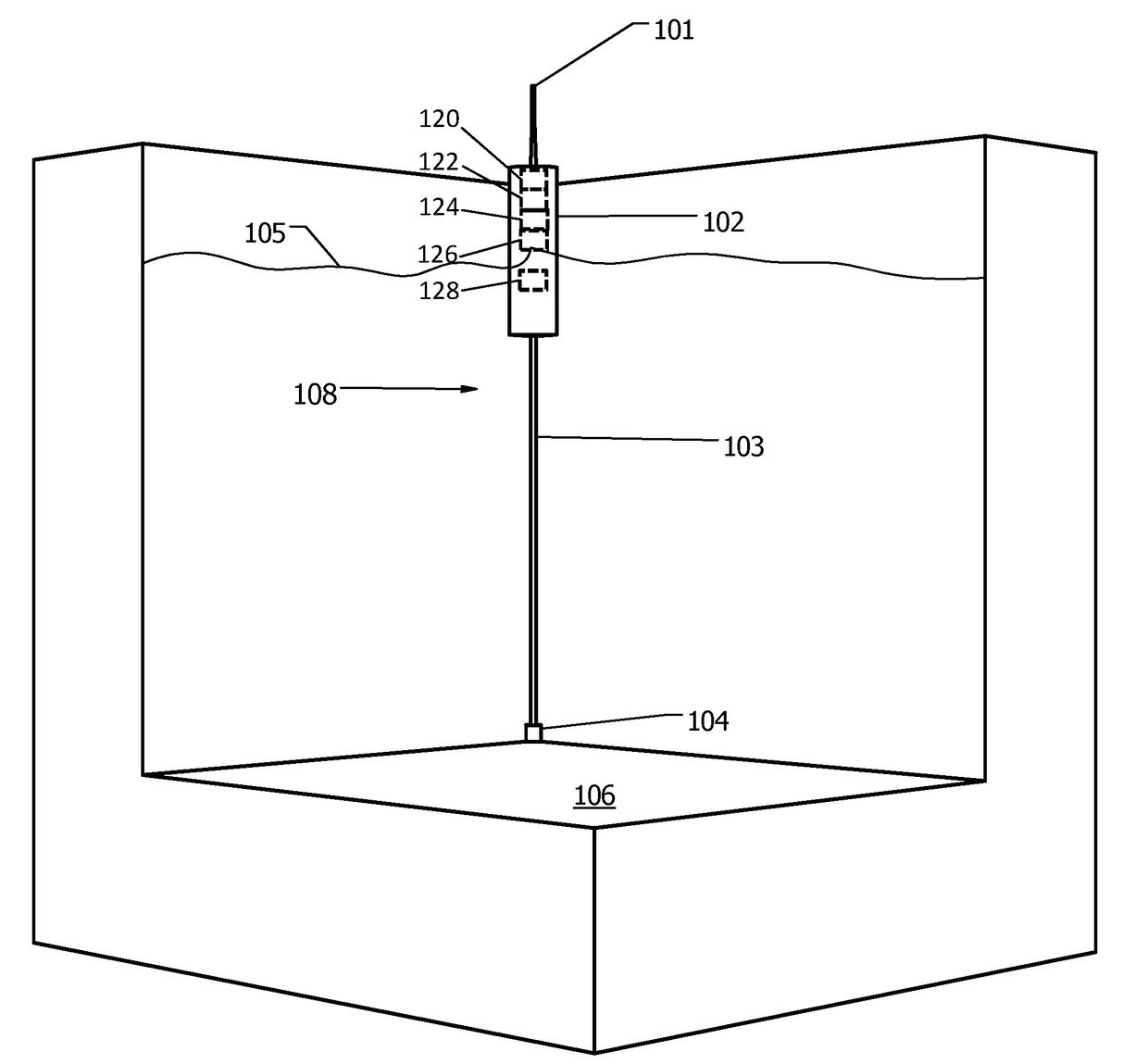
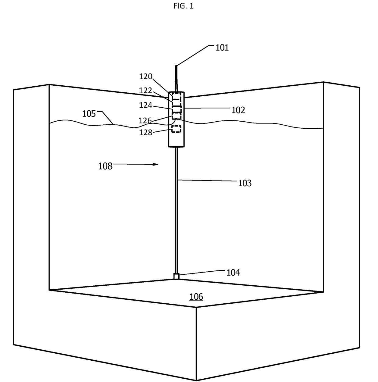
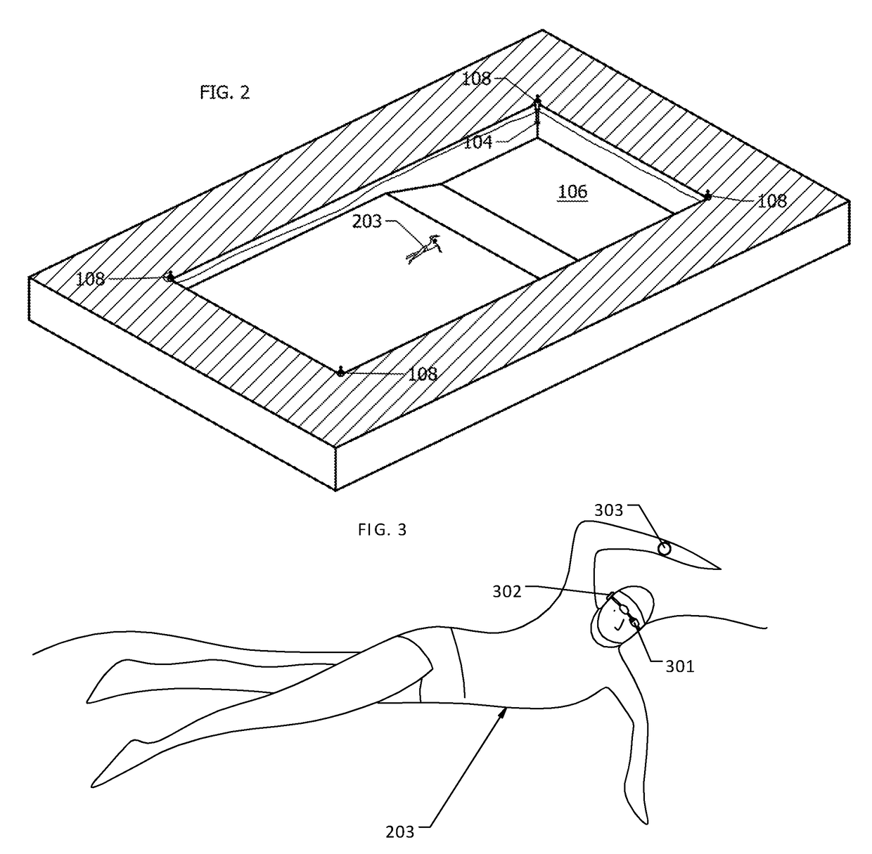
The patent describes an apparatus for measuring a swimmer's speed and conveying the information to them in real-time. The apparatus includes a plurality of ultrasonic beacons that emit signals in the water, which are then received by a wearable ultrasonic receiver on the swimmer. The receiver's microcontroller calculates the swimmer's position and speed in real-time, using the received signals. The information is then conveyed to the swimmer through a wearable user interface device, which can include a near-eye display on swimming goggles. The technical effect of this invention is the ability to accurately measure and keep track of a swimmer's pace in real-time, which can improve training and performance.

Problems solved by technology

Although objectively measured times and speed in the sport of swimming are among the most meaningful in all of sport, swimmers have little access to these measurements in their training sessions.
The sport of swimming is lacking both systems to collect instantaneous speed metrics in a practical manner and devices to present this information in real time to the swimmer.
This lack of immediate feedback denies swimmers the most effective method to learn how subtle changes in technique can improve performance.
Variations in their speed that they might have been able to correlate to changes in technique are likely to be lost in the averaging process.
This system has the same limitations as the pace clock.
The limitations of this method are that the speed information is averaged and the information is available after the lap is completed.
This system does not contemplate a method of providing instantaneous speed.
The following systems do provide instantaneous speed information but do so only in retrospect or in an impractical or cumbersome manner.
This system has the disadvantages that each swimmer must be attached to a cable, that changing direction is difficult for the swimmer, and that the cable attached to one swimmer may interfere with another swimmer's cable if multiple swimmers are using the system.
Also this system does not have a means of providing immediate speed information to the swimmer.
The system does not have a means for providing velocity information in real time to the swimmer and requires an increasing number of cameras to track multiple swimmers.
Currently this system is technically impractical with consumer grade inertial measurement units, since these units have a position error of greater than 25% of the distance traveled.
This accuracy is not sufficient.
To achieve meaningful precision using this method is economically impractical since industrial grade sensors such as Analog Devices ADIS16488 that do provide less than 1% error cost more than 1000 dollars, and one such sensor would be required for each swimmer.
As such, it suffers from the same scalability issues requiring evermore hardware to track more swimmers.
The difficulty in providing an in-goggle display for swimming is reflected in the marketplace where as of 2016 Kopin and Intel are making eyewear-attached displays for cycling, running, skiing, but have yet to produce a display module for the swimming market.
Commercially available near-eye display modules are bulky and consume 60 to more than 100 milliwatts.
These modules are not optimized to display the metrics most useful to swimming such as speed and splits, but rather are designed to render graphics with high pixel count.
Rechargeable batteries add another 1 cm3 for every hour of battery life, so a device based on this display module with a reasonable battery life is too large to be mounted on a swim goggle.
Also this module has an eye relief of 22.5 mm and it is 12.5 mm deep, so it projects 35 mm from the eye, which causes too much drag for use while swimming.

Method used


Image

  • Swimming Speedometer System with Near-Eye Display
  • Swimming Speedometer System with Near-Eye Display
  • Swimming Speedometer System with Near-Eye Display

Examples


Embodiment Construction

[0044]In the following detailed description, reference is made to the accompanying drawings that form a part hereof, and in which is shown by way of illustration, specific embodiments in which the invention may be practiced. These embodiments are described in sufficient detail to enable those skilled in the art to practice the invention, and it is to be understood that other embodiments may be utilized. It is also to be understood that structural, procedural and system changes may be made without departing from the spirit and scope of the present invention. In addition, well-known structures, circuits and techniques have not been shown in detail in order not to obscure the understanding of this description. The following detailed description is, therefore, not to be taken in a limiting sense, and the scope of the present invention is defined by the appended claims and their equivalents.

[0045]As used in the specification and in the appended claims, the singular forms “a”, “an”, and “...


PUM


Abstract

An apparatus and method for measuring a swimmer's speed and conveying the speed to the swimmer in real time includes a plurality of ultrasonic beacons each having a transducer configured to emit ultrasonic signals in a pool or other body of water within which the swimmer is swimming. A wearable, waterproof, ultrasonic receiver worn by the swimmer, receives the ultrasonic signals and generates corresponding signal data. The receiver's microcontroller captures and uses the signal data to calculate the swimmer's position and speed in real time, and conveys this information to a wearable, waterproof, user interface device worn by the swimmer, the user interface device including a near-eye display disposed on the swimmer's googles.

Description

RELATED APPLICATION[0001]This application claims the benefit of U.S. Provisional Patent Application Ser. No. 62 / 259,813 entitled Instantaneous Swimming Speedometer System, filed on Nov. 25, 2015, and claims the benefit of U.S. Provisional Patent Application Ser. No. 62 / 330,759 entitled Low-power, Near-Eye Display Module for Conveying Information by Text, filed on May 2, 2016, the contents both of which are incorporated herein by reference in their entireties for all purposes.BACKGROUND[0002]Technical Field[0003]Embodiments of the invention pertain to instantaneous feedback systems used by athletes to monitor and improve performance, and more specifically to such systems used by swimmers.[0004]Background Information[0005]Throughout this application, various publications, patents and published patent applications are referred to by an identifying citation. The disclosures of the publications, patents and published patent applications referenced in this application are hereby incorpora...

Claims


Application Information

Patent Timeline
IPC IPC(8): G01S11/14A63B71/06G06F1/16A63B33/00
CPCG01S11/14A63B33/002A63B71/0622G06F1/163G06F1/1654A63B2208/03A63B2071/0666A63B2220/30A63B2220/836A63B2244/20A63B2033/004A63B2071/0655A63B2220/13A63B2220/80A63B2225/54A63B2220/40A63B2225/50A63B2220/10A63B2210/50A63B2209/10A63B2220/833A63B2220/803A63B2220/17B63C2011/121A63B24/0062A63B2024/0071G02B2027/014G16H20/30G02B27/017G02B27/0176G02B2027/0178G01P1/08G01S5/18G01S5/30A63B2225/15A63B2071/0625A63B2220/72A63B2225/093A63B2225/02A63B2220/20A63B2220/64A63B2220/62A63B33/004G02B27/0101G02B27/0172G02B2027/0143G02B27/01G02B27/0179
Inventor TUCKER, ROBERT STEPHEN
Owner SWIMMETRIC LLC
Learn More