Method and Apparatus for Repairing a Pipe Junction

Inactive Publication Date: 2017-05-25
LMK TECH LLC
View PDF14 Cites 12 Cited by
  • Summary
  • Abstract
  • Description
  • Claims
  • Application Information

AI Technical Summary

Benefits of technology

This patent is about an improved way to seal the junction of pipes or other structures using a compression plate to secure a brim-style junction liner or a tubular liner. The brim portion of the liner is made from a resin impregnable material or is combined with the compression plate and gasket near the junction. This helps hold the liner in place without needing to rely on resin bonding. The liner can be easily and inexpensively manufactured. The method also prevents seal design failures by using a mechanical anchor that travels through both the compression plate and the structure being sealed. Additionally, the patent describes an improved method for repairing the junction of a main and lateral pipe using gaskets to prevent leakage at the penetration points of the mechanical anchors.

Problems solved by technology

However, in many known devices there is nothing to ensure the structural integrity of the brim portion, as it only conforms to a portion of the main pipe interior proximal to the junction, relying on an adhesive bond with the host pipe to ensure the integrity of the seal.
One problem with this device is that the mechanical anchors only secure the brim portion at a few selected locations thereby allowing much of the surface area of the brim portion to rely on the adhesive bond and not be mechanically secured to the interior of the pipe.
However, because the portion of the pipe liner in the main pipe covers the full circumference of the main pipe, there may be a chance of flow disruption within the main pipe near the junction with the lateral pipe in certain embodiments of the system.
Additionally, the resins used in cured-in-place pipelining are subject to polymerization shrinkage, increasing the risk of the seal being breached after installation within the pipe junction.

Method used


Image

  • Method and Apparatus for Repairing a Pipe Junction
  • Method and Apparatus for Repairing a Pipe Junction
  • Method and Apparatus for Repairing a Pipe Junction

Examples


Embodiment Construction

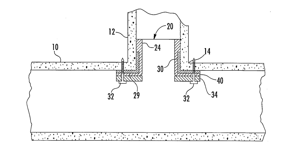
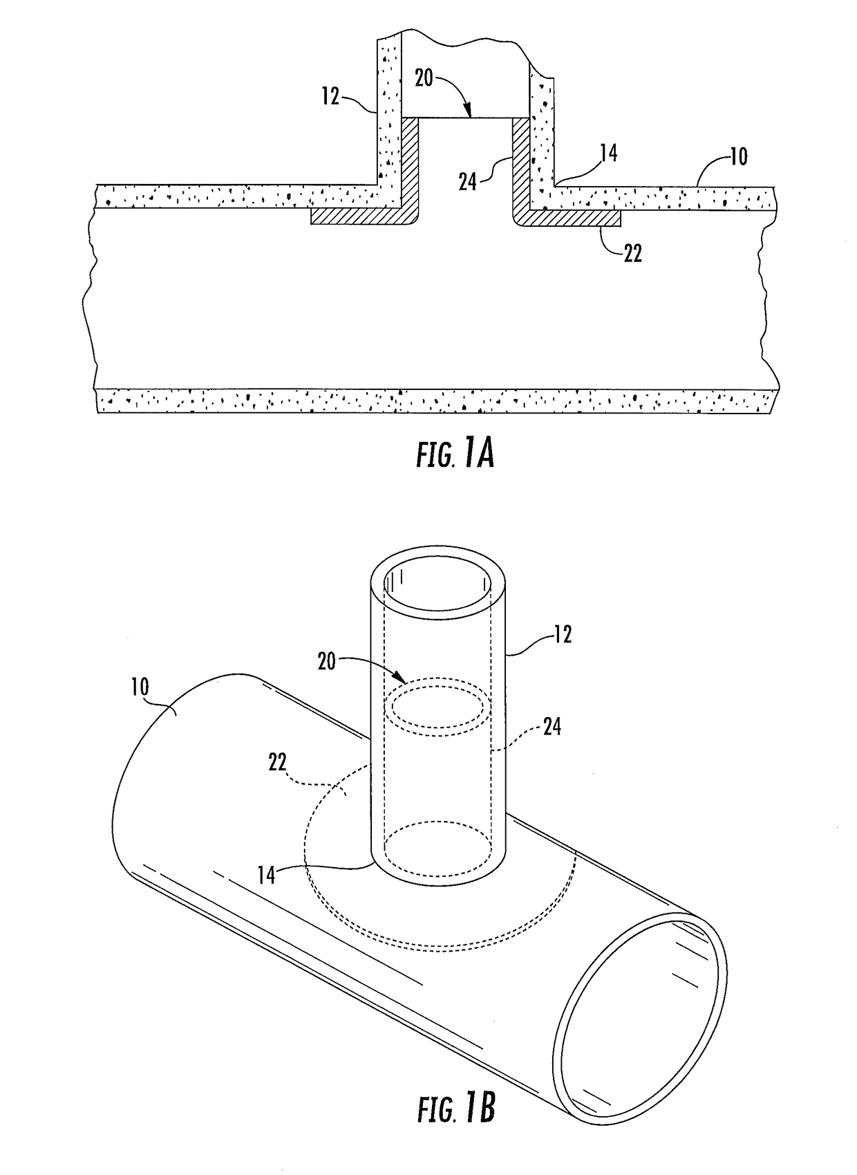
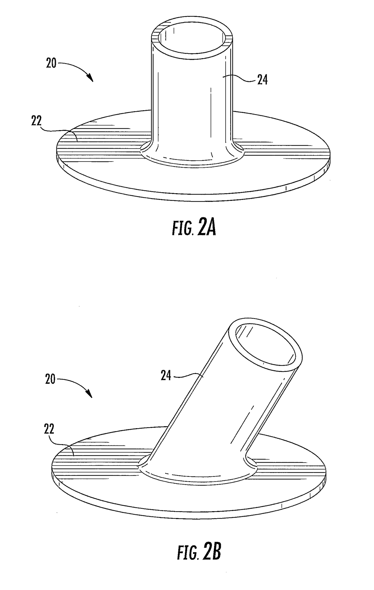
[0031]The present invention is directed towards an assembly and method for sealing a junction between tubes, passageways, conduits, or pipes. Embodiments of the invention include a pipe liner 20 having a tubular portion 24 and a brim portion 22 and a compression plate 34. The tubular portion of the pipe liner 20 is placed against an interior wall of the pipe 12 and the brim portion 22 is placed against the second structure 10. The compression plate 34 and brim portion 22 are secured to the second structure 10 using a mechanical anchor 32 so that the compression plate 34 compresses the brim portion 22 against the second structure 10. The method may further include placing a gasket 29 between the brim portion 22 of the pipe liner 20 and the second structure 10. The mechanical anchor 32 may be inserted through the gasket 29 and at least partially through the second structure 10. In some embodiments the mechanical anchor 32 is inserted through the compression plate 34 but not through th...


PUM


Abstract

An assembly and method of sealing a junction of a pipe and a second structure are provided. The assembly includes a pipe liner having a tubular portion and a brim portion, a compression plate, and a mechanical anchor adapted to secure the compression plate and brim portion of the pipe liner to the second structure. The assembly may further include a gasket for placement between the pipe liner and the pipe or second structure. The gasket may comprise a hydrophilic material, a hydrophobic material, or a compressible material. The methods of using the assembly include, but are not limited to, the use of a cured-in-place pipe liner.

Description

CROSS REFERENCE TO RELATED APPLICATIONS[0001]This application is based upon U.S. Provisional Application Ser. No. 62 / 253,199 filed Nov. 10, 2015, the complete disclosure of which is hereby expressly incorporated by this reference.FIELD OF THE INVENTION[0002]The invention relates generally to a method and assembly for repair of junctions of tubes, passageways, conduits, or pipes. More particularly, but not exclusively, the invention relates to methods and devices for repairing a pipe junction with a mechanically-anchored compression plate to create a fluid-tight seal at the junction.BACKGROUND OF THE INVENTION[0003]Many methods are currently known to rehabilitate or repair existing pipe junctions. For example, a cured-in-place pipe liner may be used to rehabilitate a pipe junction. Cured-in-place pipe liners are commonly used throughout the pipelining industry, and there are two common forms of cured-in-place pipe lining methods that have been used for the repair of the junction of a...

Claims


Application Information

Patent Timeline
IPC IPC(8): F16L55/179F16L55/165
CPCF16L55/179E03F3/04F16L41/021F16L55/165E03F2003/065
Inventor KIEST, JR., LARRY W.
Owner LMK TECH LLC
Why Eureka
Try Eureka