
System for gas compression on electric hydraulic fracturing fleets

a technology of electric hydraulic fracturing and gas compression, which is applied in the direction of machines/engines, combustion air/fuel air treatment, borehole/well accessories, etc., to achieve the effect of reducing the pressure of the natural gas stream

Pending Publication Date: 2017-05-25
US WELL SERVICS LLC
View PDF12 Cites 158 Cited by
  • Summary
  • Abstract
  • Description
  • Claims
  • Application Information

AI Technical Summary

Benefits of technology

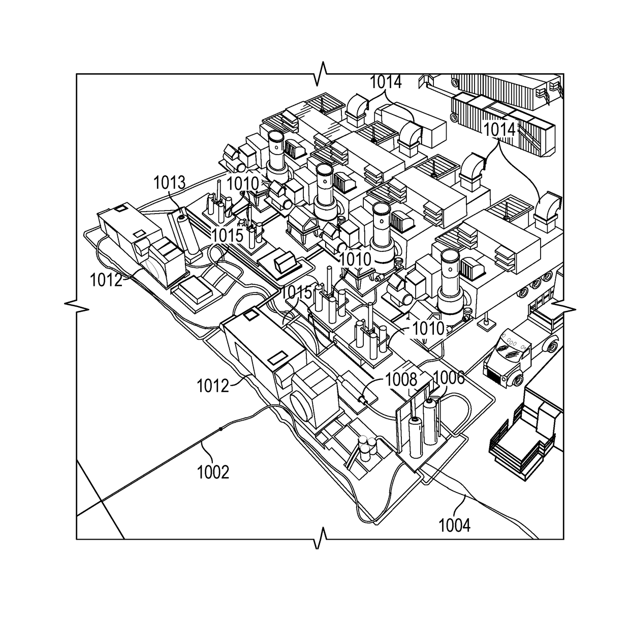
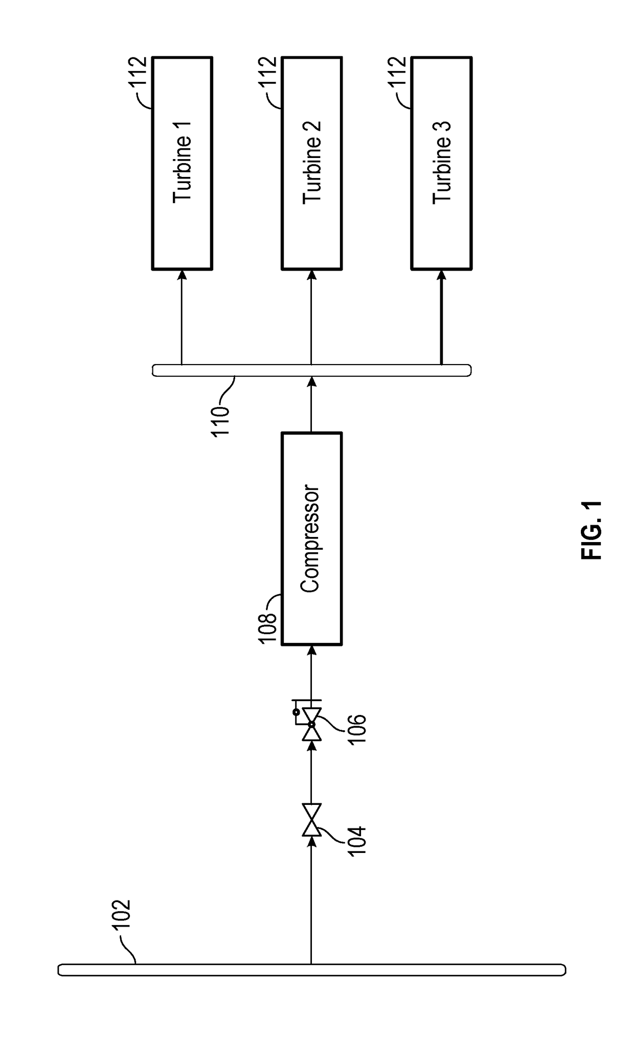
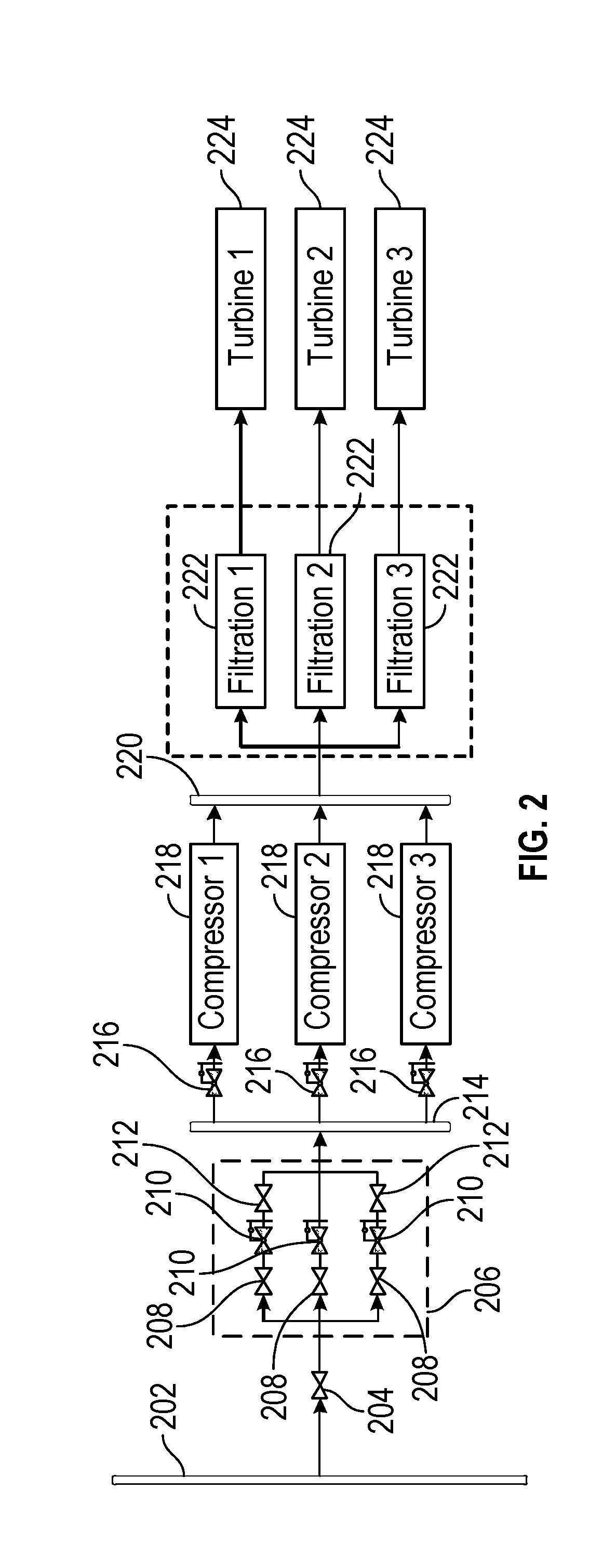
The patent describes a system and method for providing electric power to hydraulic fracturing equipment using natural gas turbine generators. The system includes a valve to control the release of natural gas from a main gas line into a turbine gas line. The natural gas stream is processed to remove sand and water, and then compressed before being sent to the turbine generators. The compressors are mobile and can be brought to different fracturing sites. The system also includes a heating element to prevent the natural gas stream from condensing, and a fuel source for the turbine generators. The technical effects of the patent include improved efficiency and reliability of the hydraulic fracturing process, reduced emissions, and reduced risk of damage to equipment.

Problems solved by technology

It may be the case that gas leaves the main supply line and enters the turbine gas line at pressures that would cause damage to the compressors.

Method used


Image

  • System for gas compression on electric hydraulic fracturing fleets
  • System for gas compression on electric hydraulic fracturing fleets
  • System for gas compression on electric hydraulic fracturing fleets

Examples


Embodiment Construction

[0034]The method and system of the present disclosure will now be described more fully hereinafter with reference to the accompanying drawings in which embodiments are shown. The method and system of the present disclosure may be in many different forms and should not be construed as limited to the illustrated embodiments set forth herein; rather, these embodiments are provided so that this disclosure will be thorough and complete, and will fully convey its scope to those skilled in the art. Like numbers refer to like elements throughout. In an embodiment, usage of the term “about” includes + / −5% of the cited magnitude. In an embodiment, usage of the term “substantially” includes + / −5% of the cited magnitude.

[0035]It is to be further understood that the scope of the present disclosure is not limited to the exact details of construction, operation, exact materials, or embodiments shown and described, as modifications and equivalents will be apparent to one skilled in the art. In the ...


PUM


Abstract

Embodiments relate to hydraulic fracturing equipment powered by one or more natural gas turbine generators. Natural gas from a supply line is released via a valve into a turbine gas line. The turbine gas line includes one or more regulators to reduce the pressure of the natural gas stream in the turbine gas line to a pressure or pressure range optimum for one or more gas compressors. The gas compressors increase the pressure of the natural gas stream, which is then directed to one or more natural gas turbine generators. The natural gas turbine generators combust the natural gas to produce electricity, which powers electric hydraulic fracturing equipment.

Description

CROSS REFERENCE TO RELATED APPLICATIONS[0001]This application claims priority to and the benefit of, co-pending U.S. Provisional Application Ser. No. 62 / 258,055, filed Nov. 20, 2015, the full disclosure of which is hereby incorporated by reference herein for all purposes.BACKGROUND OF THE INVENTION[0002]1. Field of Invention[0003]The present disclosure relates to operations in a subterranean formation. In particular, the present disclosure relates to a hydraulic fracturing system.[0004]2. Description of Related Art[0005]Hydraulic fracturing is a technique used to stimulate production from some hydrocarbon producing wells. The technique usually involves injecting fluid into a wellbore at a pressure sufficient to generate fissures in the formation surrounding the wellbore. Typically, the pressurized fluid is injected into a portion of the wellbore that is pressure isolated from the remaining length of the wellbore so that fracturing is limited to a designated portion of the formation....

Claims


Application Information

Patent Timeline
Patent Type & Authority Applications(United States)
IPC IPC(8): F02C7/05F02C7/22
CPCF02C7/05E21B43/26F02C7/22F02C6/00E21B43/2607F02C7/236
Inventor OEHRING, JAREDHINDERLITER, BRANDON N.
Owner US WELL SERVICS LLC
Learn More