Circuits and methods for controlling power amplifiers

a technology of power amplifiers and circuits, applied in the direction of gain control, control circuits for distortion reduction, high frequency amplifiers, etc., can solve the problem of system failure to address aftermarket performance variations, system failure to fully anticipate the quantity and nature of process and/or thermal performance, potential and extent of load mismatch, etc. problem, to achieve the effect of reducing power consumption for operation, and improving linearity of gain

Inactive Publication Date: 2017-05-18
SKYWORKS SOLUTIONS INC
View PDF4 Cites 12 Cited by
  • Summary
  • Abstract
  • Description
  • Claims
  • Application Information

AI Technical Summary

Benefits of technology

[0023]In some embodiments, the system can further include a variable base resistance for the driver stage. The variable base resistance can be configured to provide a base resistance value for the driver stage to facilitate the improved linearity of gain.
[0024]According to a number of implementations, the present disclosure relates to a portable communication device that includes a transmitter configured to provide a signal, a driver stage transistor configured to receive the signal, and a final stage transistor coupled to the driver stage transistor. The device further includes a current mirror configured to control a current through a terminal of the driver stage transistor based upon a current through a terminal of the final stage transistor so that a composite gain of the driver stage transistor and the final stage transistor has improved linearity of gain as a function of power output when compared to either the driver stage transistor or the final stage transistor.
[0025]In some embodiments, the current mirror can be configured to permit at least one of lower power consumption for operation of portable communication device and improvement in adjacent channel leakage ratio performance.
[0026]For purposes of summarizing the disclosure, certain aspects, advantages and novel features of the inventions have been described herein. It is to be understood that not necessarily all such advantages may be achieved in accordance with any particular embodiment of the invention. Thus, the invention may be embodied or carried out in a manner that achieves or optimizes one advantage or group of advantages as taught herein without necessarily achieving other advantages as may be taught or suggested herein.

Problems solved by technology

While these types of pre-distortion systems may have many advantages in particular applications, they also have some drawbacks.
For example, in many RF devices it is often not practical to fully anticipate the quantity and nature of process and / or thermal performance issues as well as the potential for and extent of load mismatches.
These systems are not capable of addressing aftermarket variations in performance, especially if they vary more after extended use, consumer end product modification (e.g., utilizing certain phone cases which change the thermal characteristics or antenna efficiency of the phone) and / or misuses and abuse of an RF device such as a phone.

Method used


Image

  • Circuits and methods for controlling power amplifiers
  • Circuits and methods for controlling power amplifiers
  • Circuits and methods for controlling power amplifiers

Examples


Embodiment Construction

[0034]The headings provided herein, if any, are for convenience only and do not necessarily affect the scope or meaning of the claimed invention.

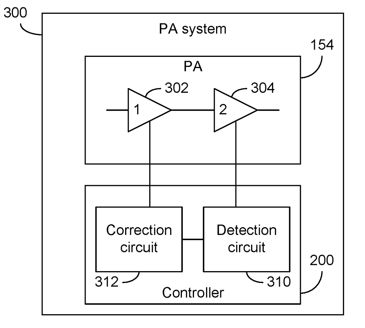
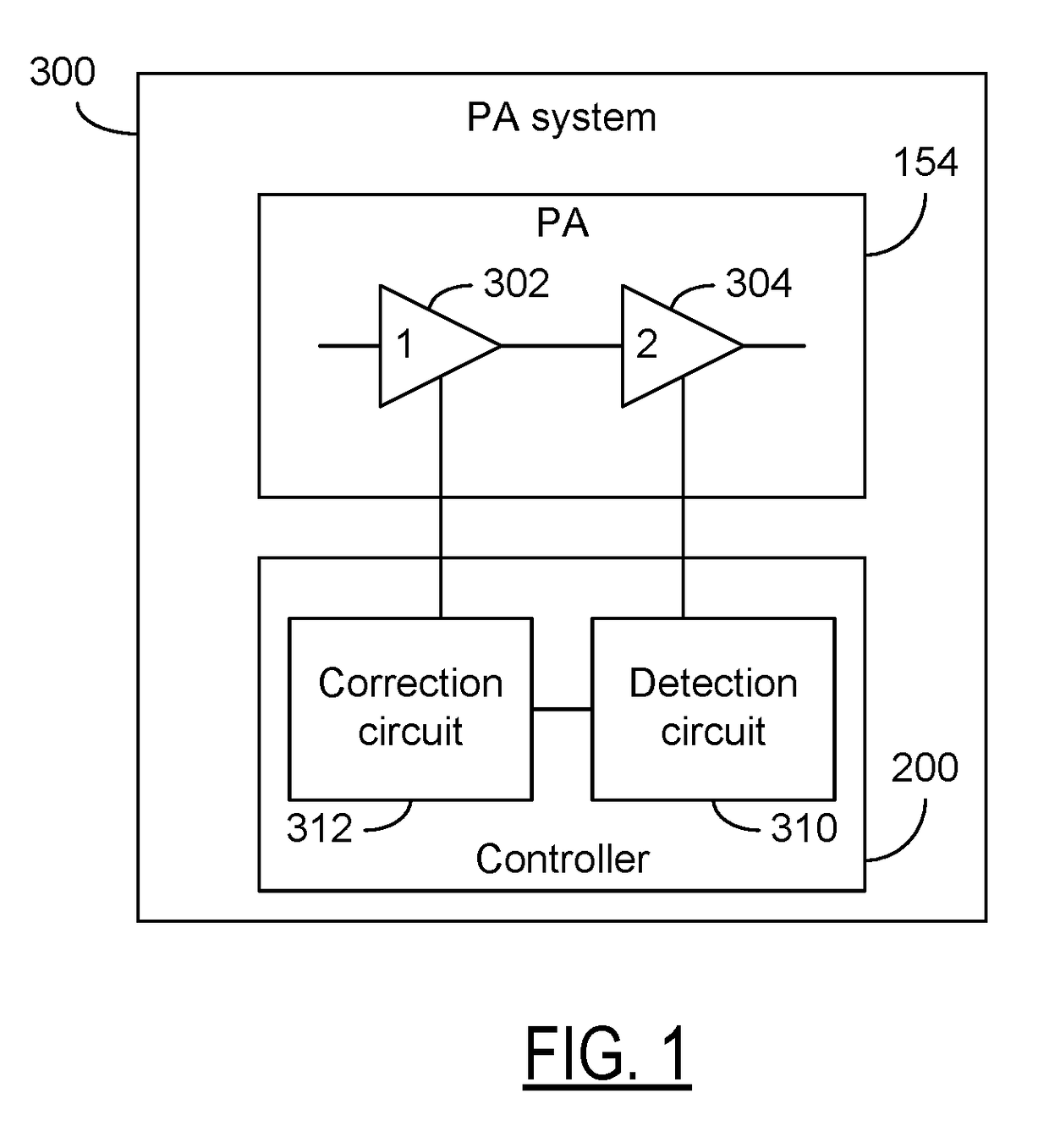
[0035]FIG. 1 shows a block diagram of a power amplifier (PA) system 300 having one or more desirable features as described herein. In some embodiments, such a PA system can include a power amplifier 154 and a controller 200. The power amplifier 154 can include a plurality of amplification stages. For example, a first stage 302 can be a driver stage, and a second stage 304 can be a final output stage. It will be understood that there may or may not be an intermediate stage between the first stage 302 and the second stage 304.

[0036]In some embodiments, an operating parameter of one amplification stage can be detected, and such an operating parameter can be utilized to generate a correction signal to adjust operation of another amplification stage. Such a cooperation of detection and correction between the two amplification stages can provide ...


PUM


Abstract

Circuits and methods for controlling power amplifiers. In some embodiments, a power amplification system can include a first amplification stage configured to operate with a first bias signal, and a second amplification stage configured operate with a second bias signal. The power amplification system can further include a control circuit coupled to the first amplification stage and the second amplification stage. The control circuit can be configured to generate the first bias signal based on the second bias signal. Such a first bias signal can result in the first stage having a gain profile that compensates for either or both of a gain expansion and gain compression of the second amplification stage.

Description

CROSS-REFERENCE TO RELATED APPLICATION(S)[0001]This application claims priority to U.S. Provisional Application No. 62 / 255,600 filed Nov. 16, 2015, entitled METHOD AND APPARATUS FOR EXTENDING POWER AMPLIFIER OUTPUT LINEARITY AND EXTENDING BATTERY LIFE AND CONTROLLING ADJACENT CHANNEL LEAKAGE PERFORMANCE FOR MOBILE COMMUNICATION DEVICES, the disclosure of which is hereby expressly incorporated by reference herein in its respective entirety.BACKGROUND[0002]Field[0003]The present disclosure relates to circuits and methods for controlling power amplifiers, including AM-AM compensation of power amplifiers as they approach saturation.[0004]Description of the Related Art[0005]In some radio-frequency (RF) applications, open loop pre-distortion of an input signal to two-stage power amplifiers are utilized to compensate for gain expansion and compression near power amplifier saturation. Such designs typically monitor the input power and adjust the gain of a driver stage to compensate for the ...

Claims


Application Information

Patent Timeline
Patent Type & Authority Applications(United States)
IPC IPC(8): H03F1/02H04B1/04H03G3/30H03F3/19H03F3/24
CPCH03F1/0205H03F3/19H03F2200/451H03G3/3042H04B1/04H03F3/245H03G1/04H03F1/0261H03F2200/18H03F2200/411H04B1/0475
Inventor LEHTOLA, PHILIP JOHN
Owner SKYWORKS SOLUTIONS INC
Why Eureka
Try Eureka