
Wave Energy Reduction System

a technology of wave energy and reduction system, which is applied in the direction of piers, breakwaters, groynes, etc., can solve the problems of plant leaves being mechanically damaged, difficult, if not impossible, to be reestablished on their own without reducing wave energy, and death of the plant itsel

Inactive Publication Date: 2017-05-18
MELBY III PHILIP OLOUS
View PDF12 Cites 3 Cited by
  • Summary
  • Abstract
  • Description
  • Claims
  • Application Information

AI Technical Summary

Benefits of technology

The present invention provides a method and apparatus for reducing wave energy in a way that allows salt marsh wetland grasses to endure and establish without needing to completely eliminate waves or restricting sediment passage. This invention is different from other solutions because it attempts to abate wave energy, not eliminate it altogether. It uses lightweight, readily accessible materials that are easy to transport and inexpensive to obtain. The invention also allows water to pass through the wave energy reduction barrier, further aiding in the prevention of shoreline erosion. The technical effects of this invention are to protect emergent salt marsh wetland grasses from wave energy without incurring any of the problems or deficiencies associated with prior solutions.

Problems solved by technology

In many coastal locations where S. alterniflora and other salt marsh wetland grasses once existed, excessive wave energy in coastal waters due to conditions such as increased boating traffic and the creation of deeper channels makes it difficult, if not impossible, for such grasses to be reestablished on their own without reducing wave energy.
Attempts to establish salt marsh wetland grasses along the shoreline without wave reduction typically result in mechanical damage to the plant leaves and, ultimately death to the plant itself.
As a result, the failure to reestablish salt marsh wetland grasses compounds the problem of shoreline erosion.
Several solutions currently exist for preventing shoreline erosion, but these methods hardly address the issue of reestablishing emergent salt marsh wetland grasses.
Such barriers are expensive to purchase, difficult to place, and difficult to remove.
Concrete is heavy, and as such, the time and manpower to add these barriers can be prodigious.
This solution, while capable of abating wave energy, creates the costly step of packing fibers into the tubular casing.
Furthermore, such fiber logs are difficult, if not impossible, to reuse since they are biodegradable.
Beyond this, the logs restrict the accumulation of sediment around the salt-marsh wetland grasses, thereby undermining the very stability of these grasses.
As such, they do not aid in the establishment of emergent salt marsh wetland grasses.
Although these methods and apparatuses would slow the flow of water, thereby reducing wave energy, like the Spangler apparatus, they would also restrict the flow of sediment to the salt-marsh wetlands grasses, thereby undermining the stability of these grasses.
Most require the inclusion of some type of fill material, making them relatively complex to construct and often impractical for installation and removal by limited numbers of personnel.
Also, the use of fill material will necessarily limit the amount of sediment allowed to pass through the barriers, which in turn will compromise the establishment of emergent salt marsh wetland grasses.
This shares the same problem as the teaching of Carpenter (U.S. Pat. No. 7,695,219), viz: a blanket placed flat on the ground is largely useless for protecting salt marsh wetland grasses from wave energy.

Method used


Image

  • Wave Energy Reduction System
  • Wave Energy Reduction System
  • Wave Energy Reduction System

Examples


Embodiment Construction

[0029]The preferred embodiment of the invention is described as follows:

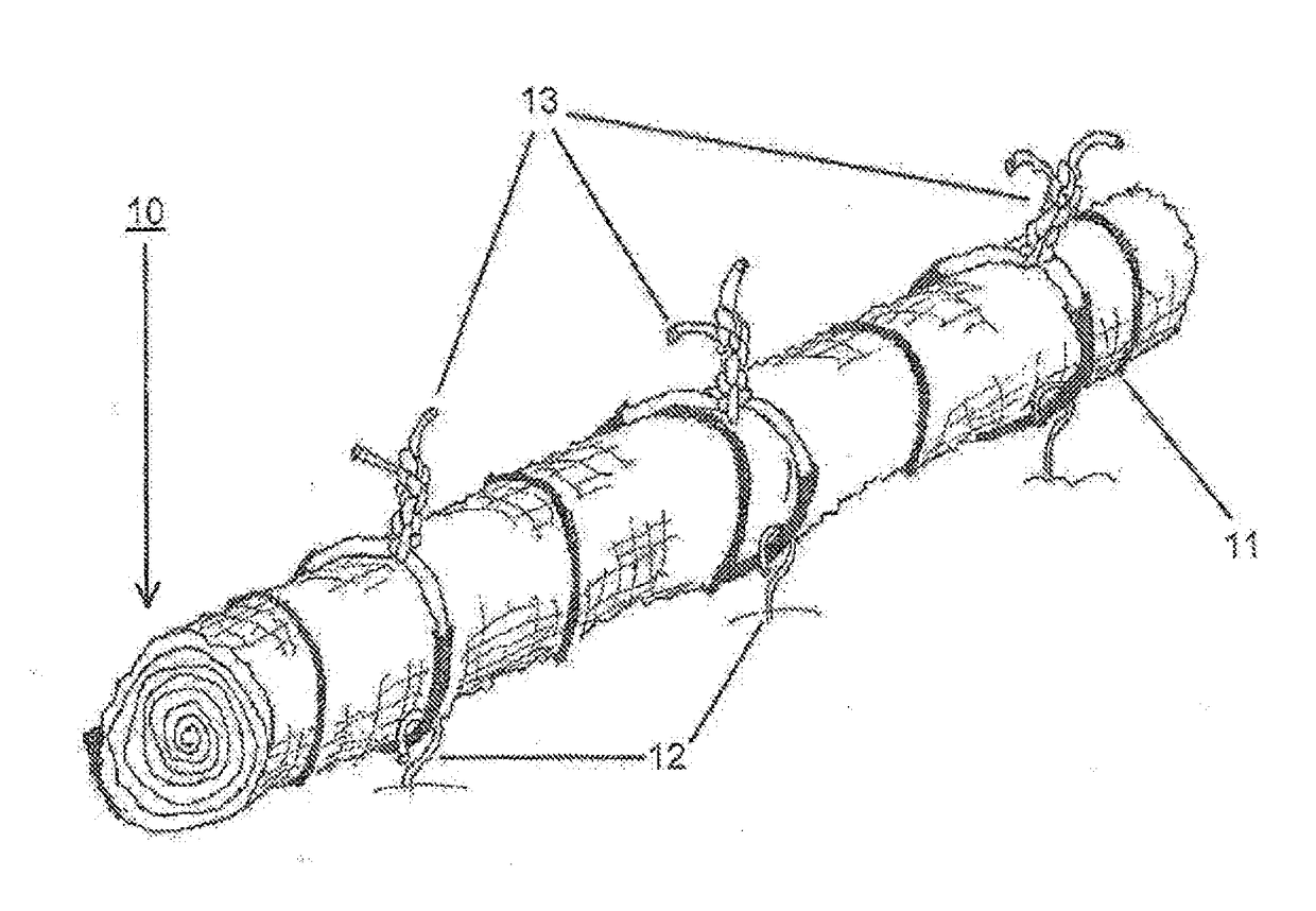
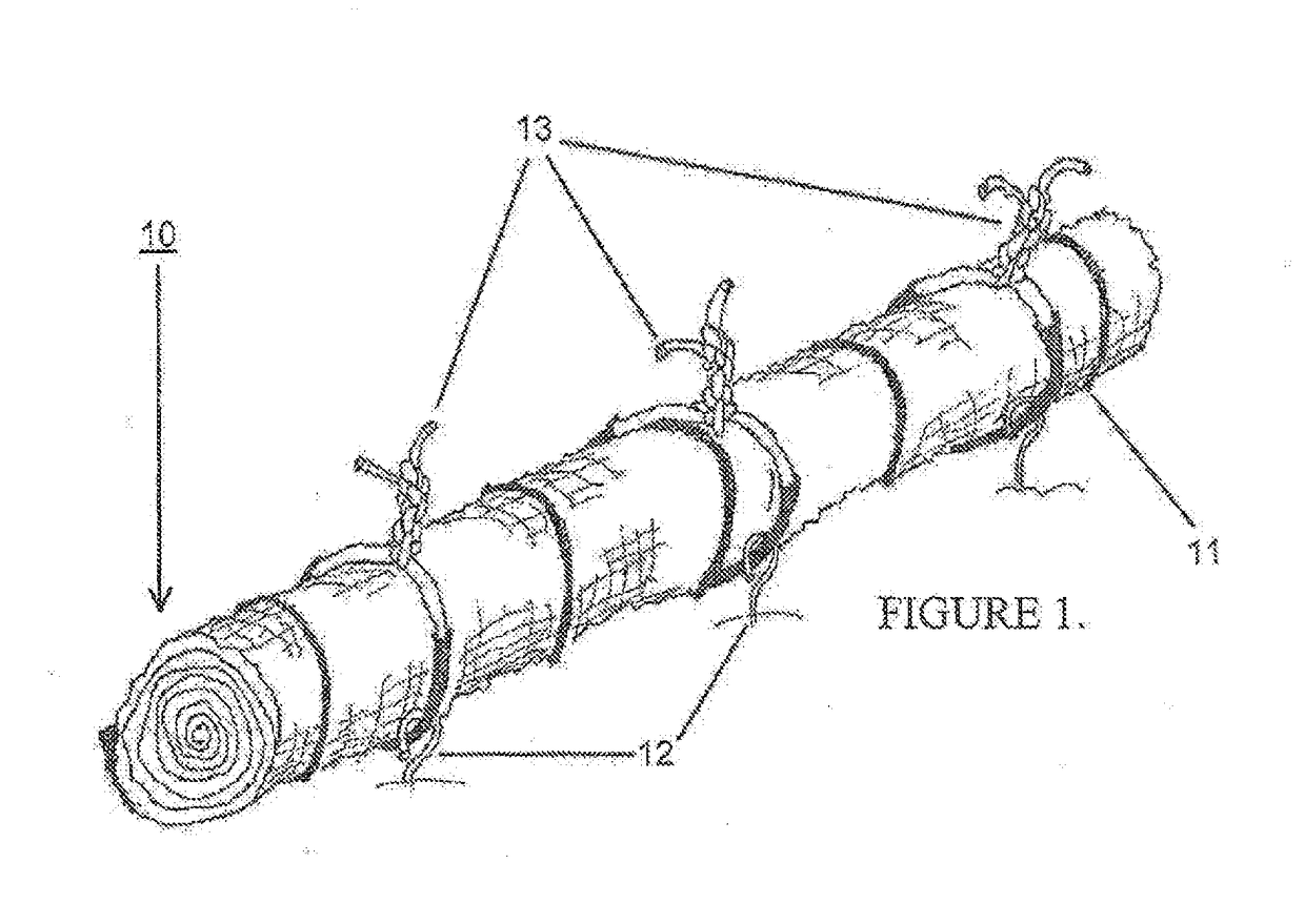
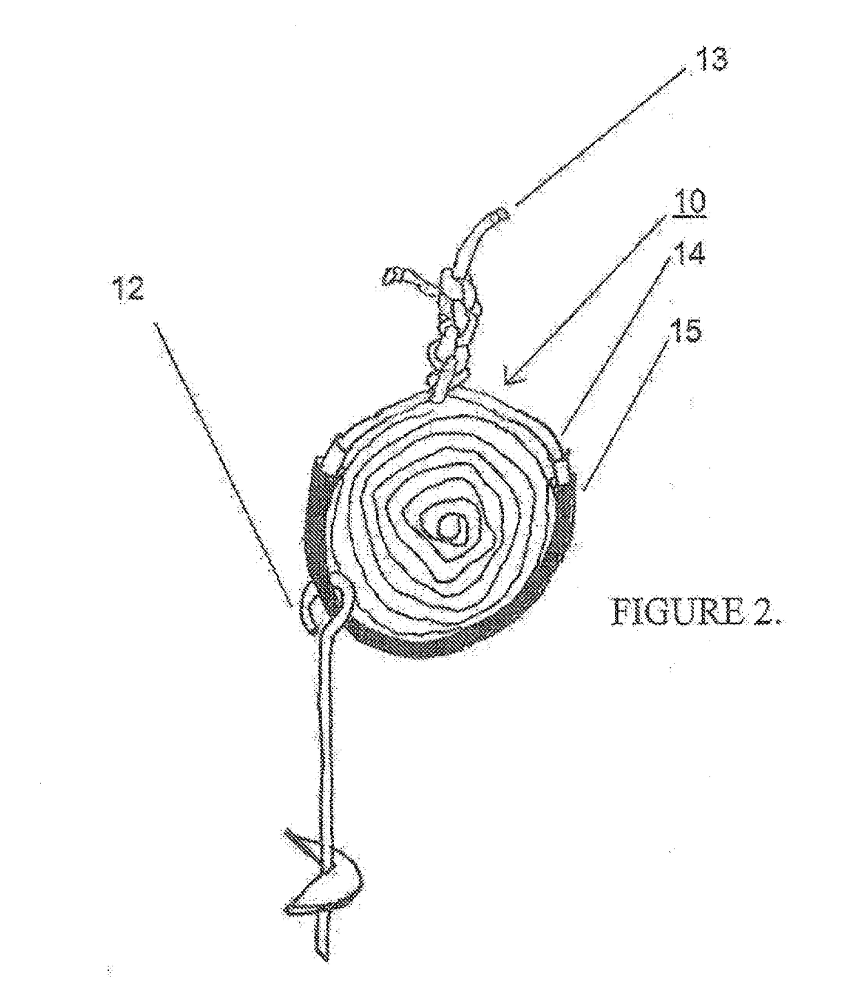
[0030]To create the wave energy reduction system 10, assemble 8-feet-by-27 feet (2.44 m×8.2 m) of geotextile fabric having a porosity of at least 95% and no flocculant into a cylindrical roll that is 12-14 inches (30-36 cm) in diameter and 8 feet (2.44 m) in length. The roll is tied together with black cable ties 11 to maintain the cylindrical shape of the roll. Tie the roll together with 48-inch (1.22 m) long and ¼-inch (6.35 mm) wide black cable ties. The black cable ties should have ultraviolet light inhibitors and a 175 psi (1.21 MPa) tensile stress rating. Locate the two end-of-the-roll cable ties 12 inches (30.5 cm) from each end of the roll. Evenly space the remaining cable ties 18 inches (45.72 cm) apart along the roll. Cable ties will be pulled tightly against the geotextile fabric to secure the material into a rolled form.

[0031]When setting the wave reduction system in position, place them in water tha...


PUM


Abstract

A method and apparatus for creating moderately quiescent water in which salt marsh wetland grasses can endure and eventually establish without the need for the total elimination of the energy of occurring waves or the restriction of sediment passage

Description

CROSS REFERENCE TO RELATED APPLICATIONS[0001]This application is a continuation-in-part (CIP) of U.S. application Ser. No. 14 / 568,418, filed on Dec. 12, 2014, which is a continuation-in-part (CIP) of and claims the benefit of U.S. application Ser. No. 13 / 847,342, filed on Mar. 19, 2013, which claims the benefit of U.S. Provisional Application No. 61 / 614,455, filed Mar. 22, 2012, wherein all of these priority applications are incorporated herein by reference in their entirety.STATEMENT REGARDING FEDERALLY SPONSORED RESEARCH OR DEVELOPMENT[0002]Not applicable.REFERENCE TO SEQUENCE LISTING, A TABLE, OR A COMPUTER PROGRAM LISTING COMPACT DISC APPENDIX[0003]Not applicable.BACKGROUND OF THE INVENTION[0004]The present invention relates generally to a wave energy reduction method and apparatus for creating moderately quiescent water in which planted emergent salt marsh wetland grasses can endure and eventually become established. To this end, the present invention reduces wave energy withou...

Claims


Application Information

Patent Timeline
Patent Type & Authority Applications(United States)
IPC IPC(8): E02B3/06E02B3/12
CPCE02B3/06E02B2201/02E02B3/122E02B3/04E02B3/125Y02A10/00Y02A20/404
Inventor MELBY, III, PHILIP OLOUS
Owner MELBY III PHILIP OLOUS
Learn More