
Apparatus and Method for Network Flow Scheduling

a network flow and applicability technology, applied in the field of network and telecommunications, can solve the problems of congested network spots that require operator attention, reduced network throughput for best effort traffic, and congestion of network spots, so as to reduce link utilization

Active Publication Date: 2017-05-04
HUAWEI TECH CANADA
View PDF1 Cites 44 Cited by
  • Summary
  • Abstract
  • Description
  • Claims
  • Application Information

AI Technical Summary

Benefits of technology

The patent text describes two methods for network flow scheduling. The first method is designed to minimize the number of links in the multicast tree, which is used to send multicast traffic from a source to multiple destinations. By replacing one or more of the links based on their link utilization, the method aims to reduce the tree cost while ensuring that all destinations receive the necessary bandwidth. The second method, on the other hand, is designed to maximize the use of link capacity by replacing one or more of the links based on their link depth in the multicast tree. This method takes into account both the link utilization and the tree cost to ensure that all destinations receive the necessary bandwidth while keeping the tree cost low. These methods can be implemented using an apparatus described in the patent text. The technical effects of these methods include improved network efficiency and reduced latency for multicast traffic delivery.

Problems solved by technology

Shortest path flow scheduling, however, tends to congest the shortest path links.
Therefore it may reduce network throughput for best effort traffic, and it may create congested network spots that require operator attention.
It also may block new flow establishment.

Method used


Image

  • Apparatus and Method for Network Flow Scheduling
  • Apparatus and Method for Network Flow Scheduling
  • Apparatus and Method for Network Flow Scheduling

Examples


Embodiment Construction

[0013]The making and using of the presently preferred embodiments are discussed in detail below. It should be appreciated, however, that the present invention provides many applicable inventive concepts that can be embodied in a wide variety of specific contexts. The specific embodiments discussed are merely illustrative of specific ways to make and use the invention, and do not limit the scope of the invention.

[0014]Various Internet based applications require flow and path scheduling throughout a network infrastructure. For example, in a network supporting Internet Protocol Television (IPTV) for digital terrestrial television (DTTV), ad hoc services and on demand multicast, and best effort services, information is delivered to transmit stations or to homes in the form of packets through a network. Typically, the packet traffic is sent from a source, e.g., a server where the programming data is stored, to multiple end or destination points. Due to the nature of the networks in quest...


PUM


Abstract

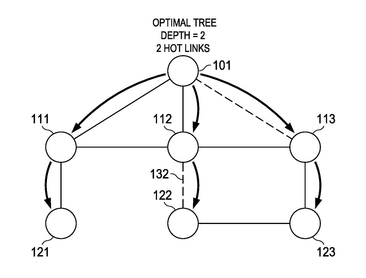
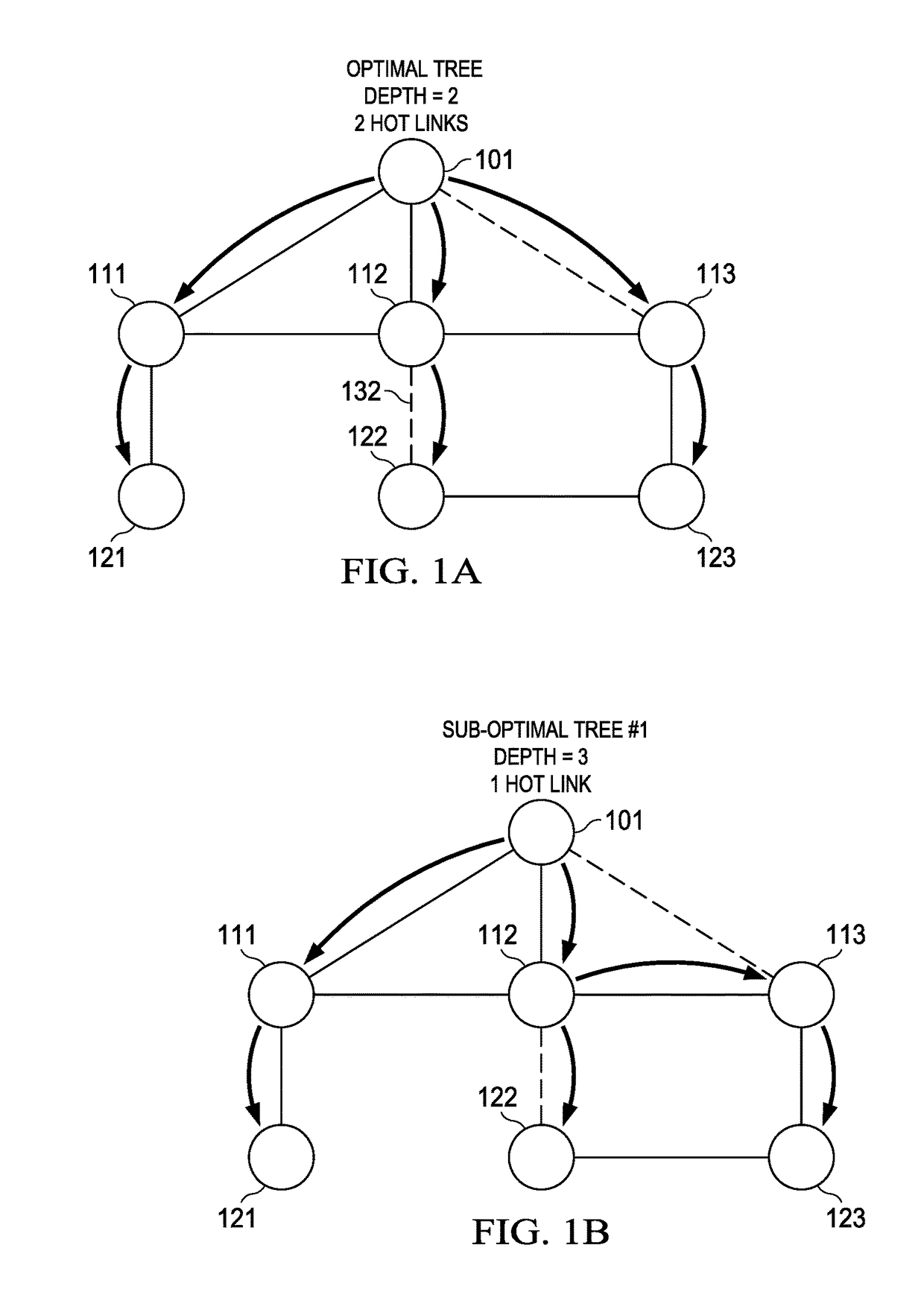
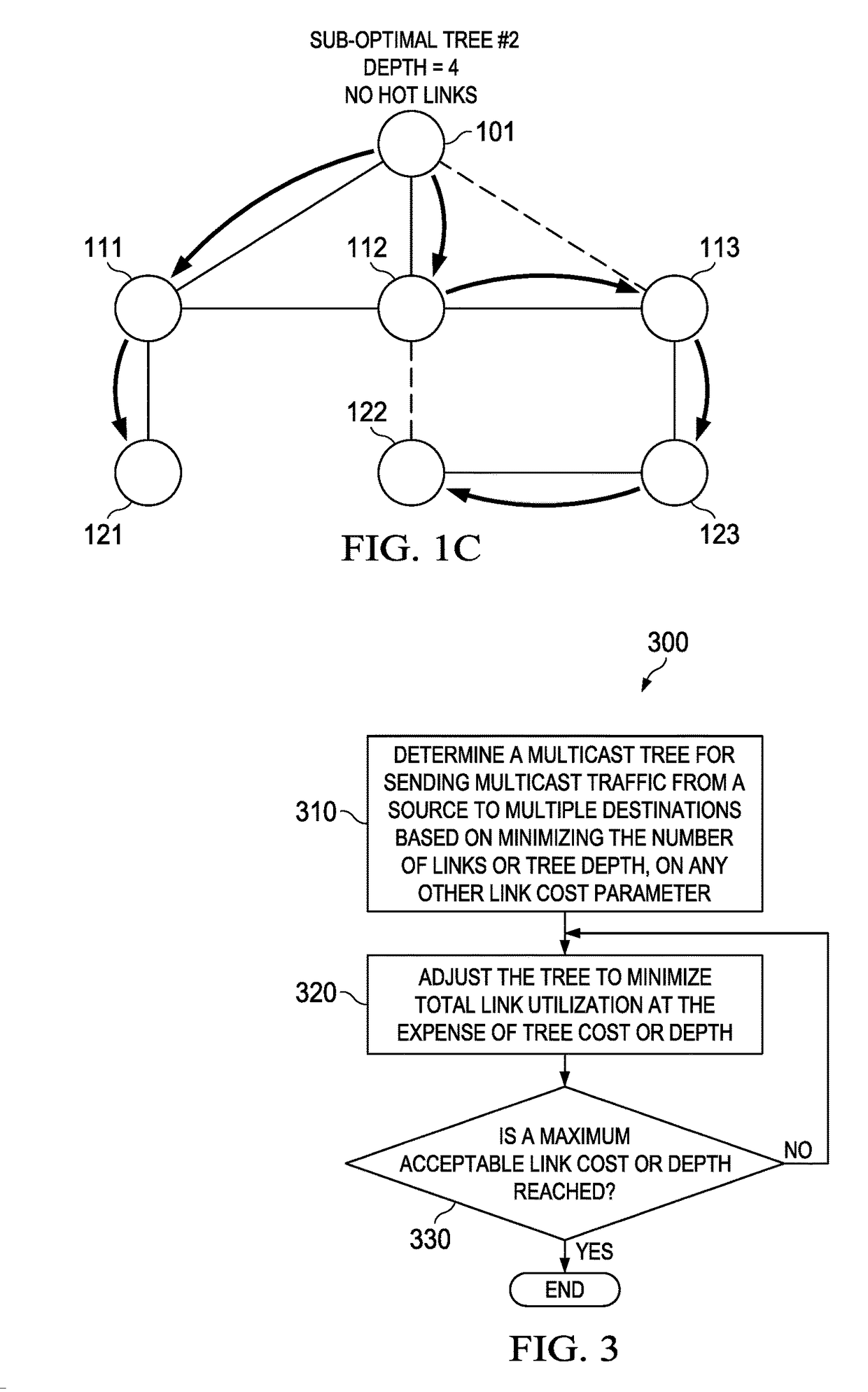
Embodiments are provided for path flow scheduling of multicast traffic through a network. The paths for traffic flow are determined to optimize link utilization in terms of bandwidth and link capacity, and limit link cost. In an embodiment, a method is implemented for network flow scheduling. The method includes establishing, by a controller of a network, a multicast tree which includes a plurality of links for sending multicast traffic from a source to multiple destinations. The tree is established based on minimizing a number of links in the multicast tree. The tree is then adjusted by replacing one or more of the plurality of links to reduce the link utilization. The tree adjustment is repeated by further replacing one or more links in the multicast tree to further reduce the link utilization.

Description

[0001]This application claims the benefit of U.S. Provisional Application No. 62 / 250,820 filed on Nov. 4, 2015 by William Carson McCormick et al. and entitled “System and Method for Network Flow Scheduling,” which is hereby incorporated herein by reference as if reproduced in its entirety.TECHNICAL FIELD[0002]The present invention relates to networking and telecommunications, and, in particular embodiments, to an apparatus and method for network flow scheduling.BACKGROUND[0003]Generally, wired and wireless internet communications are provided by connections via one or more links between network nodes. These connections can be wired or wireless, and can include both access network and backhaul connections. The nodes connected can include wireless access points such as base stations, user equipment, routers, optical devices and other core network nodes. The links are used to provide an end-to-end communications connection. A mechanism such as multiprotocol label switching (MPLS) may b...

Claims


Application Information

Patent Timeline
Patent Type & Authority Applications(United States)
IPC IPC(8): H04L12/18H04L12/753H04L12/723H04L45/16H04L45/50
CPCH04L12/189H04L45/48H04L45/50H04L12/185H04L12/1877H04L45/125
Inventor MCCORMICK, WILLIAM CARSONASHWOOD-SMITH, PETERKELLY, FRANCIS PATRICK
Owner HUAWEI TECH CANADA
Learn More