
Reduction of leakage current from supercapacitor by modifying electrode material

a supercapacitor and electrode material technology, applied in hybrid capacitor separators, hybrid capacitor electrolytes, hybrid/edl manufacture, etc., can solve the problems of less satisfactory electric performance of the supercapacitor, and achieve the effects of enhancing the capacity of storing charges, reducing leakage current, and prolonging the retention of ions

Active Publication Date: 2017-05-04
CYNTEC
View PDF1 Cites 6 Cited by
  • Summary
  • Abstract
  • Description
  • Claims
  • Application Information

AI Technical Summary

Benefits of technology

The present invention aims to enhance the ability of a supercapacitor to store charges and improve its performance by reducing leakage current and lengthening the retention of ions on the electrodes even if the voltage supply is interrupted.

Problems solved by technology

On the other hand, larger the leakage current requires more power for maintaining the voltage and results in less satisfactory electric performance of the supercapacitor.

Method used


Image

  • Reduction of leakage current from supercapacitor by modifying electrode material
  • Reduction of leakage current from supercapacitor by modifying electrode material
  • Reduction of leakage current from supercapacitor by modifying electrode material

Examples


Embodiment Construction

[0019]The present invention will now be described more specifically with reference to the following embodiments. It is to be noted that the following descriptions of preferred embodiments of this invention are presented herein for purpose of illustration and description only; it is not intended to be exhaustive or to be limited to the precise form disclosed.

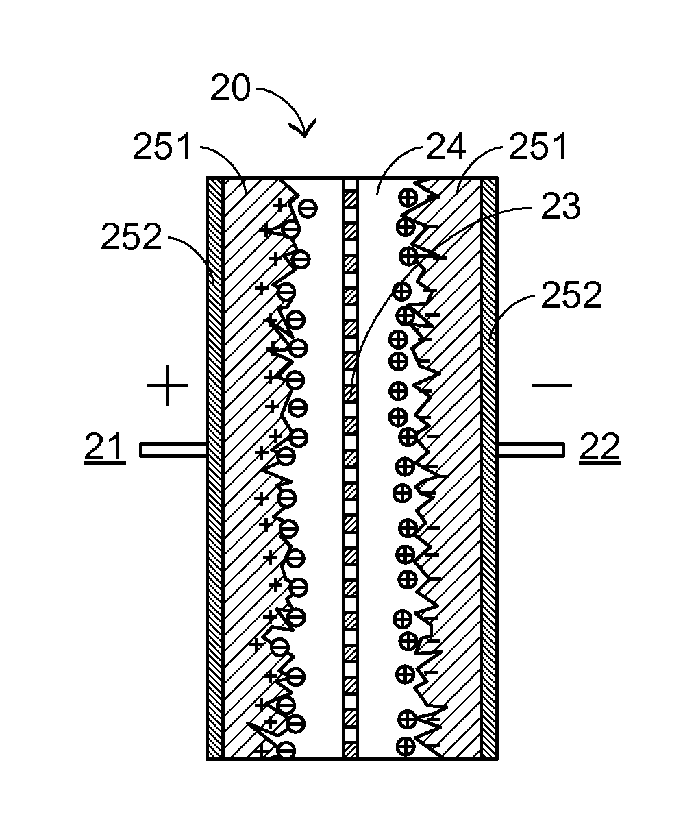
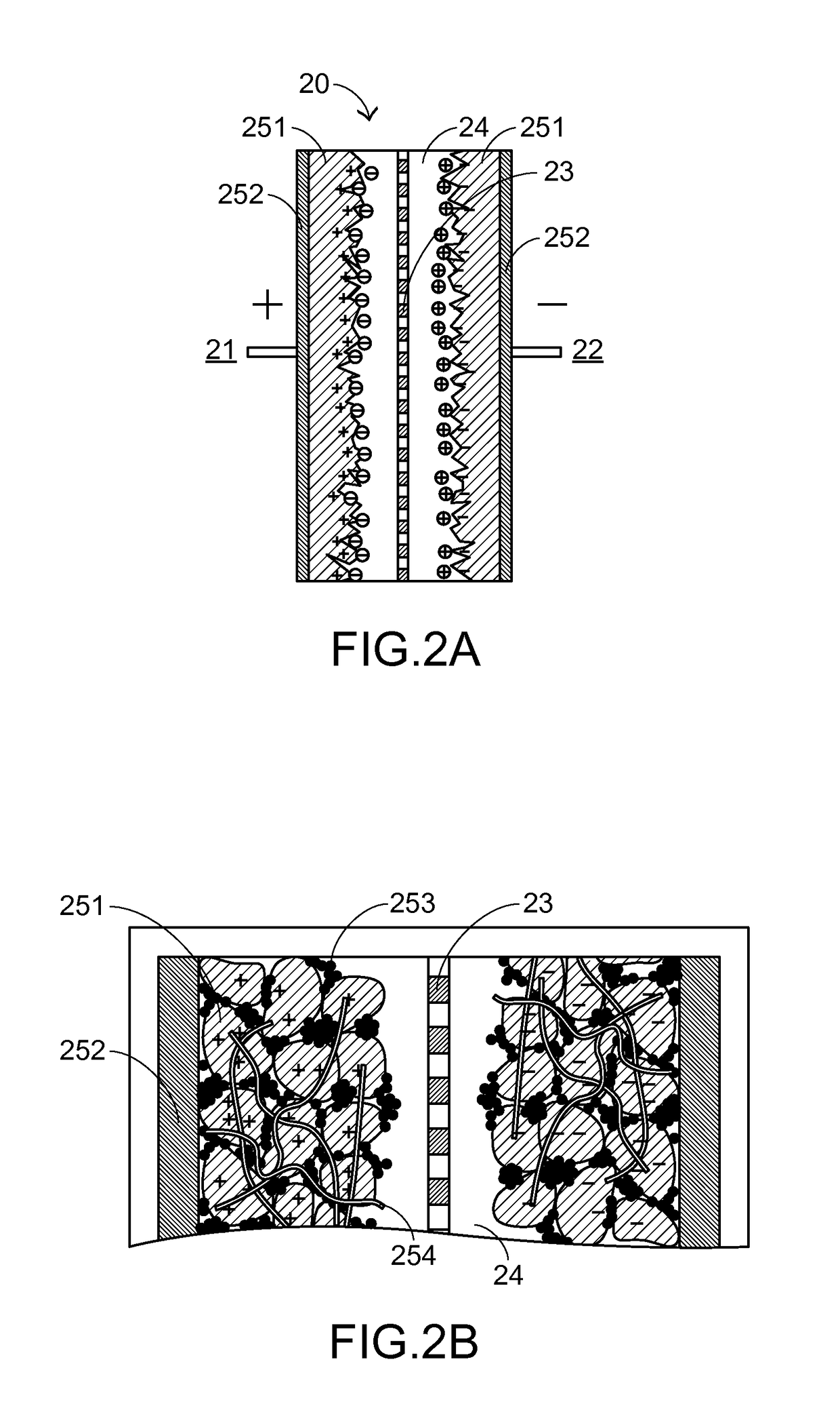
[0020]Referring to FIG. 2A, a supercapacitor unit of a supercapacitor according to an embodiment of the present invention is schematically illustrated. The structure of the supercapacitor unit 20 includes an anode 21, a cathode 22, a separator 23 and an electrolyte 24. Each of the anode 21 and the cathode 22 is constructed by applying a porous electrode material 251 onto a conductive current-collecting substrate 252. The separator 23 is disposed between and separates the anode 21 and the cathode 22. The electrolyte 24 rinses the electrodes 21 and 22, and the separator 23. While being continuously supplied with a voltage V, the el...


PUM

PropertyMeasurementUnit
leakage currentaaaaaaaaaa

Abstract

A composite material of an electrode unit includes: a porous electrode material being 50˜95 wt % of the composite material; an electret material being greater than O wt % and less than 15 wt % of the composite material; a dispersant material being 0˜15 wt % of the composite material; an adhesive material being 0˜15 wt % of the composite material; an electric conduction auxiliary agent being greater than O wt % and less than 30 wt % of the composite material. The porous electrode material includes porous particles and the electret material is distributed among the porous particles.

Description

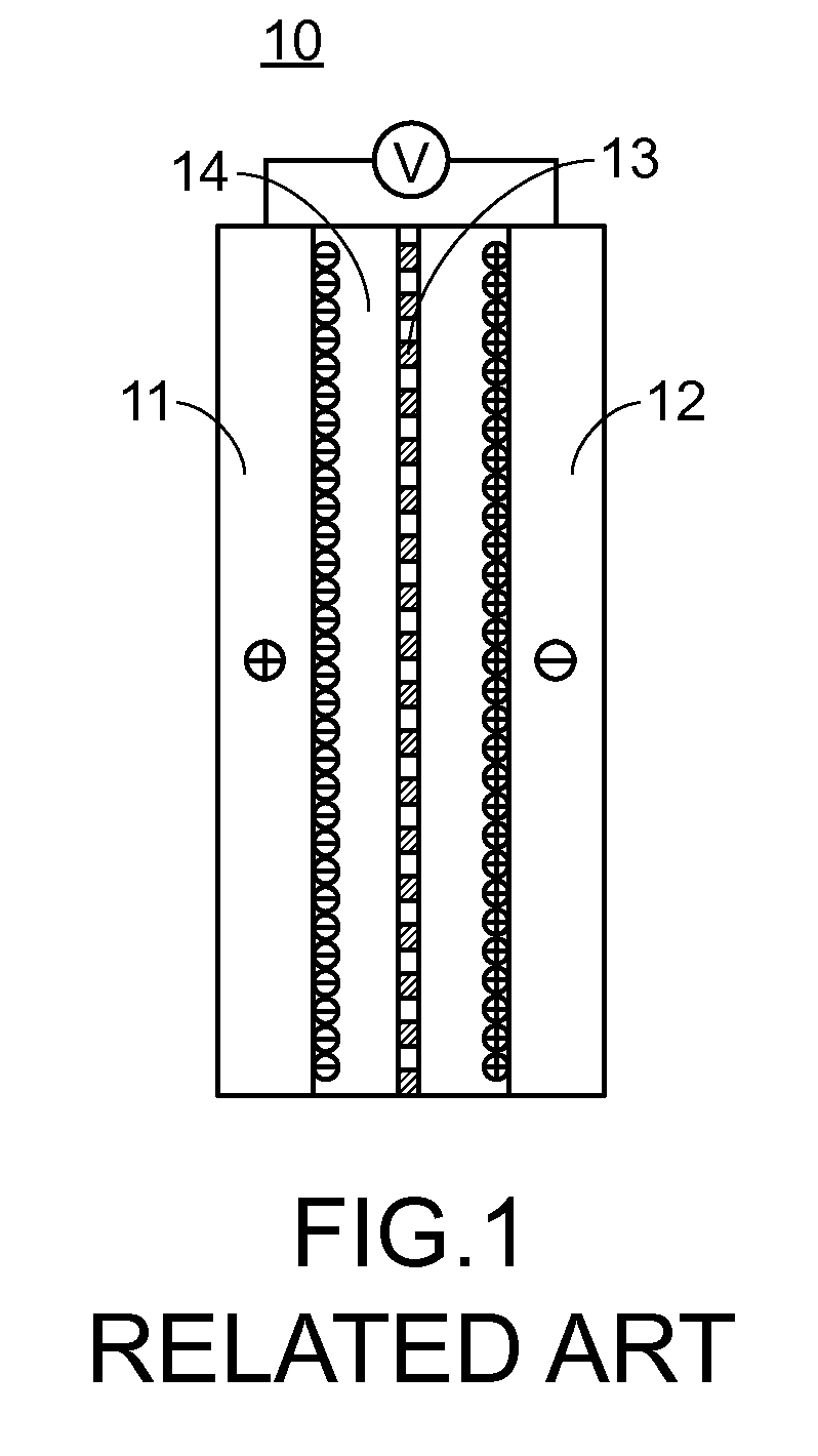
FIELD OF THE INVENTION[0001]The present invention relates to a composite material of an electrode, and more particularly to a composite material of an electrode unit of a supercapacitor. The present invention also relates to a method of producing an electrode unit made of the composite material. The present invention further relates to a supercapacitor including the electrode unit.BACKGROUND OF THE INVENTION[0002]A supercapacitor is a specific type of energy storage device which is getting more and more popular due to capabilities of high speed charging / discharging and high current / power output. A typical structure of a supercapacitor unit 10 of a supercapacitor is schematically shown in FIG. 1, which includes an anode 11, a cathode 12, a separator 13 and an electrolyte 14. Each of the anode 11 and the cathode 12 is made of activated carbon, which is porous so as to have relatively large area. The separator 13 is disposed between and separates the anode 11 and the cathode 12 for sep...

Claims


Application Information

Patent Timeline
Patent Type & Authority Applications(United States)
IPC IPC(8): H01G11/38H01G11/86H01G11/58H01G11/28H01G11/52
CPCH01G11/38H01G11/28H01G11/86H01G11/58H01G11/52H01G11/24H01G11/30Y02E60/13
Inventor CHEN, YUEH-LANGLUO, YING-DAJUANG, JUNG-YANG
Owner CYNTEC
Learn More