
Sheathless Guide Catheter Assembly

a catheter and guide technology, applied in the direction of catheters, surgery, trocars, etc., can solve the problems of requiring a larger puncture/access opening, trauma to the vessel, and taking longer to close the sheath

Active Publication Date: 2017-04-27
MEDTRONIC VASCULAR INC
View PDF6 Cites 132 Cited by
  • Summary
  • Abstract
  • Description
  • Claims
  • Application Information

AI Technical Summary

Benefits of technology

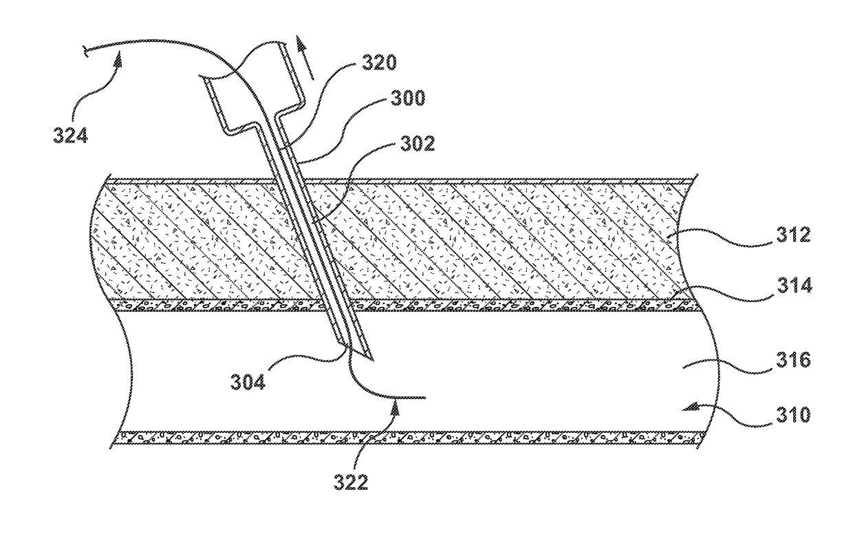
The patent text describes a guide catheter assembly that includes a dilator and a guide catheter. The dilator is a thin tube with a distal opening and a side exit port, which can be used to access a vessel in a patient. The guide catheter is a thin tube with a guide lumen that can hold the dilator. The assembly is designed to allow a needle to be inserted through a wall of a vessel and a wire to be inserted through the needle into the vessel. The wire is then removed and replaced with a dilator, which can be guided through the vessel to a desired location. The guide catheter is then inserted over the dilator and through the needle opening. A second wire can be inserted through the dilator to facilitate the placement of the guide catheter in the vestibule of the vessel. The guide catheter can be used to deliver other medical devices or fluids to the patient. The technical effect of the guide catheter assembly is to provide a reliable and safe method for accessing a vessel and delivering medical devices to a desired location.

Problems solved by technology

Such steps may cause trauma to the vessel.
While using an introducer sheath typically reduces tissue damage from catheter exchanges therethrough, the sheath requires a larger puncture / access opening, which takes longer to close after the procedure.
However, sheaths are still used, which require additional exchanges and can cause trauma to the access site of the vessel.

Method used


Image

  • Sheathless Guide Catheter Assembly
  • Sheathless Guide Catheter Assembly
  • Sheathless Guide Catheter Assembly

Examples


Embodiment Construction

[0014]Specific embodiments of the present invention are now described with reference to the figures, wherein like reference numbers indicate identical or functionally similar elements. The terms “distal” and “proximal” when used in the following description to refer to a catheter or dilator are with respect to a position or direction relative to the treating clinician. Thus, “distal” and “distally” refer to positions distant from or in a direction away from the clinician and “proximal” and “proximally” refer to positions near or in a direction toward the clinician.

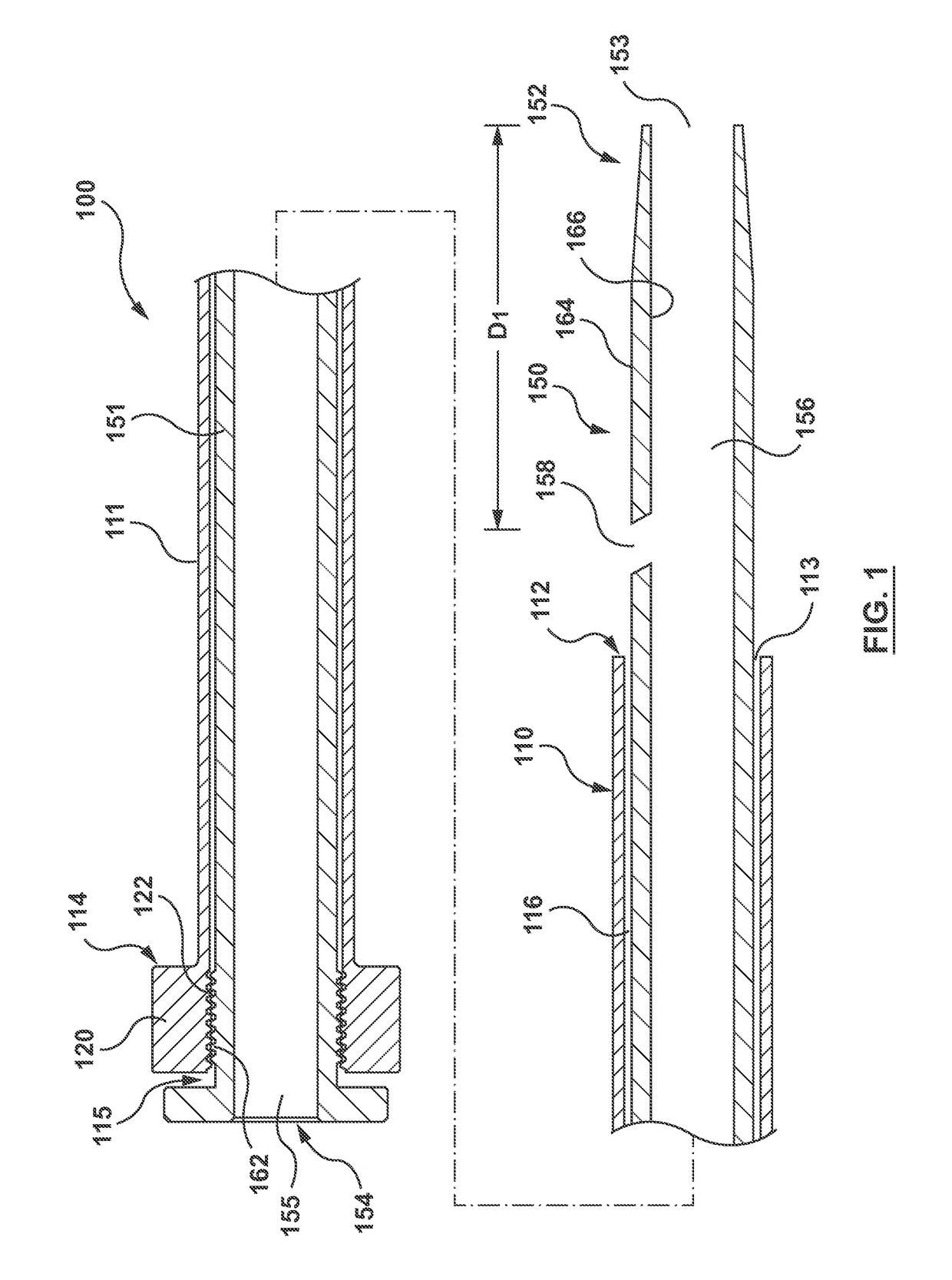
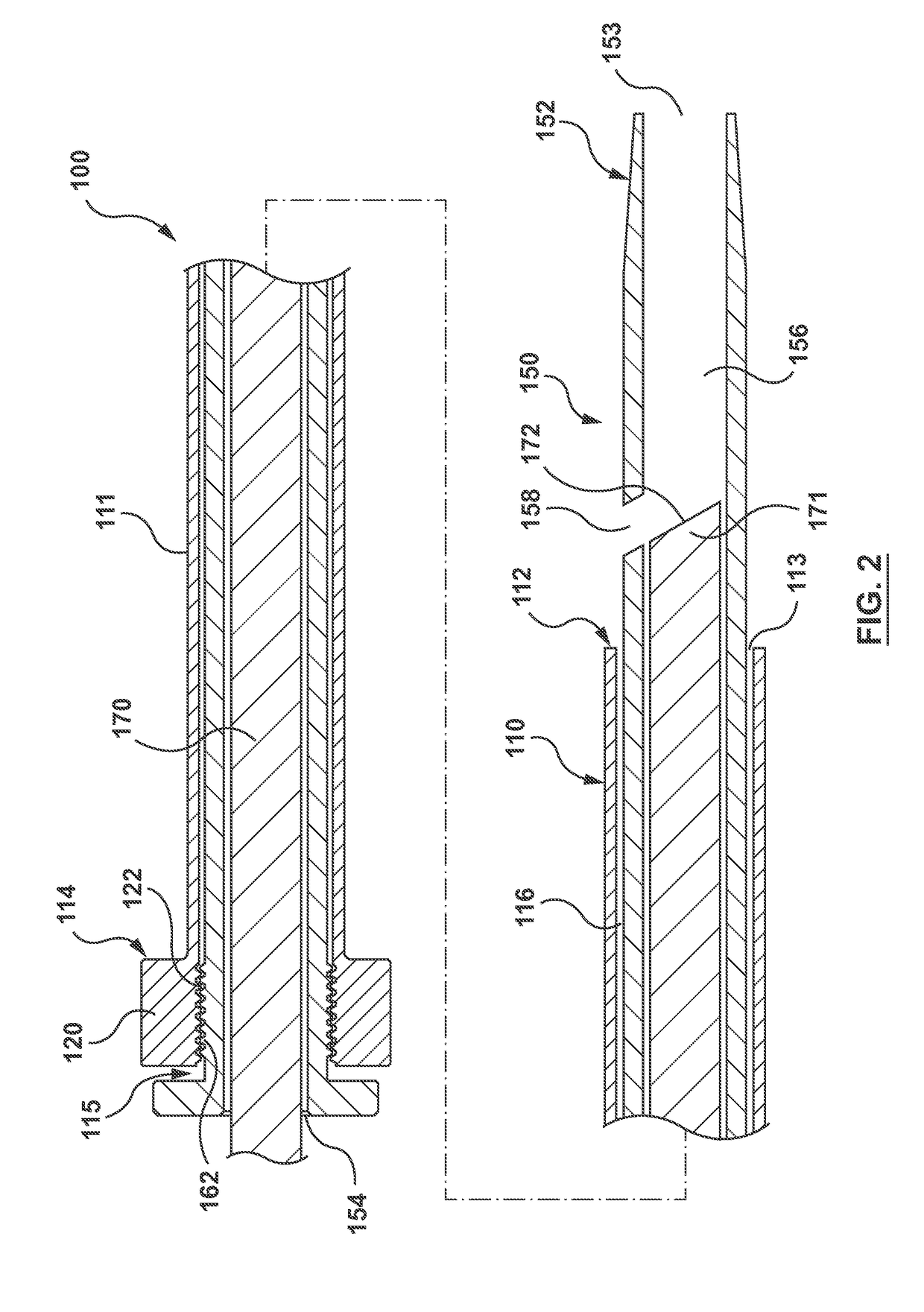
[0015]FIG. 1 shows a guide catheter assembly 100 according to an embodiment hereof. Guide catheter assembly 100 includes a guide catheter 110 and a dilator 150. Guide catheter 110 includes a generally tubular guide shaft 111 including a distal end 112, a proximal end 114, and a guide lumen 116 extending through guide shaft 111. Guide lumen 116 extends from a proximal opening 115 at proximal end 114 to a distal opening 113 ...


PUM


Abstract

A guide catheter assembly includes a dilator and a guide catheter. The dilator includes a dilator lumen extending from a distal opening at a distal end to a proximal opening at a proximal end, and a side exit port proximal of the distal opening and in communication with the dilator lumen. The guide catheter includes a proximal end, a distal end, and a guide lumen extending therebetween. The dilator and the guide lumen are sized such that the dilator can pass through the guide lumen. The dilator and the guide catheter are sized such that with the proximal end of the dilator generally aligned along an axis with the proximal end of the guide catheter, the distal end of the dilator extends distally past the distal end of the guide catheter and the side exit port is disposed distal of the distal end of the guide catheter.

Description

FIELD OF THE INVENTION[0001]Embodiments hereof relate to sheathless guide catheter assemblies and methods of using such sheathless guide catheter assemblies.BACKGROUND OF THE INVENTION[0002]Percutaneous transluminal catheterization procedures such as angioplasty, stent implantation, stent-graft implantation, and other prosthesis implantations require minimally invasive access to a patient's vasculature. Generally access is into an artery such as the common femoral artery using the Seldinger technique. A guide catheter is then advanced over a guidewire to a desired site in the vasculature near a treatment site. Procedural devices may then be advanced through the guide catheter to the treatment site.[0003]The process for gaining repeated access to the vessel can include several steps with a hollow needle, medical guidewires, guidewire exchanges, introducer sheaths, and exchanges thereof. Such steps may cause trauma to the vessel. While using an introducer sheath typically reduces tiss...

Claims


Application Information

Patent Timeline
Patent Type & Authority Applications(United States)
IPC IPC(8): A61M25/06A61M29/02A61B17/34A61M25/09
CPCA61M25/0606A61M25/09A61M2025/0024A61B17/34A61M29/02A61M25/0068A61M25/0102A61M25/0662A61M29/00A61M2025/0079A61M2025/018
Inventor STEINGISSER, H. ALLANBERTHIAUME, WILLIAMBERGLUND, JOSEPHFLANNERY, CONORVALDOVINOS, MARIA
Owner MEDTRONIC VASCULAR INC
Learn More